top of page

Progress Log
Week 14: 8/7 - 8/13 - This marks the beginning of Senior Design
On the fourteenth week:
Jon
Jon did bench testing and assembly of the Magnetic Lock. This was done to verify that the components do work out of box and to also take current and voltage measurements.
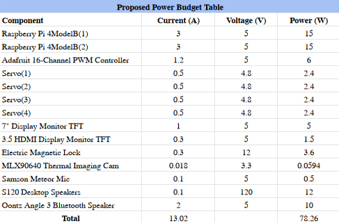
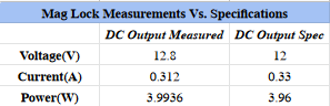
As seen above from the Mag Lock Measurements Vs. Specification table, the actual Power reading from the magnetic lock is almost a third of a watt higher than what was previously calculated as seen in the Proposed Power Budget Table. This may be due to the gauge of wire used from the power supply to the magnetic lock. A test with a larger gauge wire is needed to verify this.
Charlie
Encountered issues with booting the Raspberry Pi 4. After some troubleshooting by testing the micro SD card in different computers, he discovered that it was a hardware issue with the micro SD card. After taking a closer look at the chip, he was able to determine that a hairline crack was the cause of the reading error.
Charlie ordered a two pack of micro SD cards to be shipped overnight. Once the cards were received, he reinstalled Raspberry Pi OS on the Raspberry Pi.
By following a tutorial online, Charlie was able to install TensorFlow and OpenCV on the Raspberry Pi.
(INSERT TUTORIAL VIDEO HERE)
OpenCV was installed quickly, but TensorFlow required some troubleshooting. After some research, the problem was solved by downgrading the protobuf package to 3.9.2. The current version was 4.21.5 which was incompatible with Python3.
Group


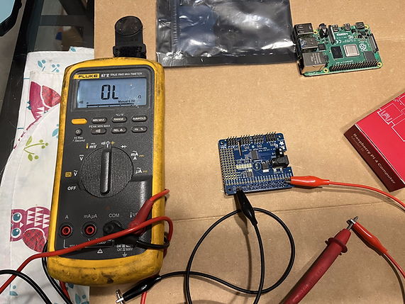
Started to stage some of the items. A cable with a ground prong is used to power the PSU for the Mag Lock. There is no ground wire for the PSU, so the ground from the cable was attached to the chassis of the PSU.
Output DC Voltage is being measured here with a Fluke 87 multi meter. Here a reading of 12.18Vdc is seen from COM to NC. NC is where the mag lock would be connected.

Input AC Voltage is being measured. Voltage reading of 122.6 Vac is measured from Hot to Neutral(Black wire to White wire)


The magnetic lock was opened and the wire landing can be seen to the right of the unit.
Wire is needed to connect the PSU to the magnetic lock so the ends of the wires were stripped and tinned so that it makes a solid connection with no wire strands poking out.
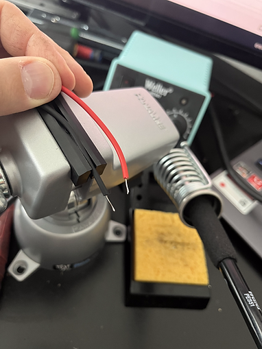
Red and black wires are tinned. The colors were kept so that polarity is not accidentally switched.


The magnetic lock is energized and that is noted with the illuminated red LED magnetic lock.
The Fluke multi meter is set to measure current. DC is measured by placing the meter in series with the circuit that energizes the magnetic lock. A reading of 312 mA is seen. A good pry and tug was done to take the steel plate off the magnetic lock but to no avail. A true test would have to be conducted to make sure that door cannot open.
Week 13: 7/31 - 8/6
On the thirteenth week:
Group
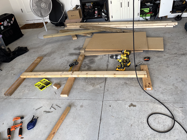
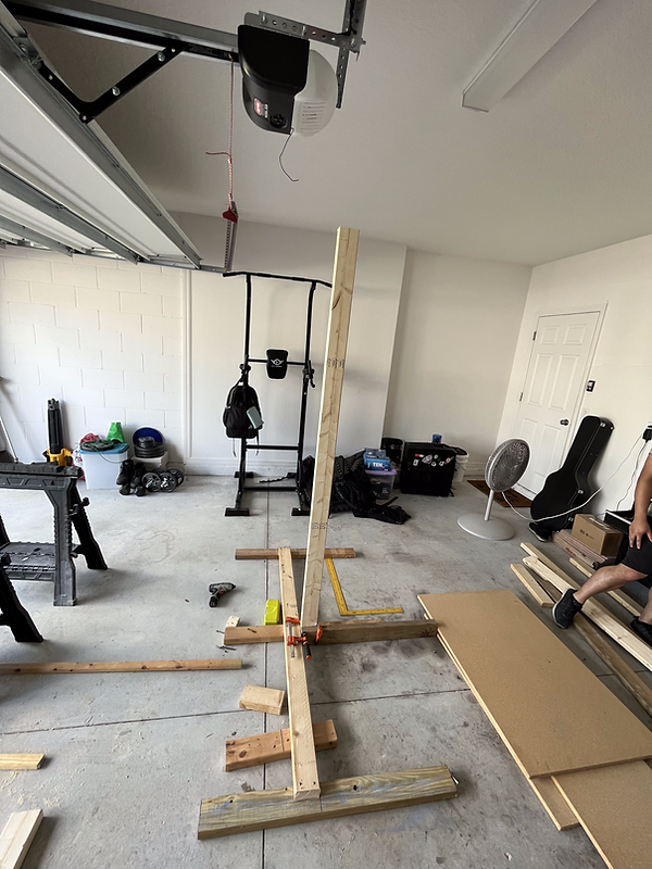
Assembled the skeleton structure that consists of the door panel and the frame that will be used as a mock door system for medical facilities. The idea was to follow the 3D rendering of the mock up designed three weeks prior. The hinges of the door were installed on the outside, so that the door swings outwards. This safety issue will be addressed. What is left is to make minor adjustments to make sure the structure is squared up and to start installing the components.
Various tools were used such as
- Saw Horse
- Circular Saw(Skil Saw)
- Jigsaw
- Speed Square
- Tape Measure
- Drill
- Impact Drill


Staging necessary pieces of wood to cut.

First portion of the frame screwed together.
Bottom of frame finished.
First vertical 2x4 mounted to the base. The farthest right piece of wood for the base was removed and replaced with a longer piece for stability.


Left photo shows us installing the left most vertical 2x4. The right photo shows the speed square being used to make sure the frame is squared up.
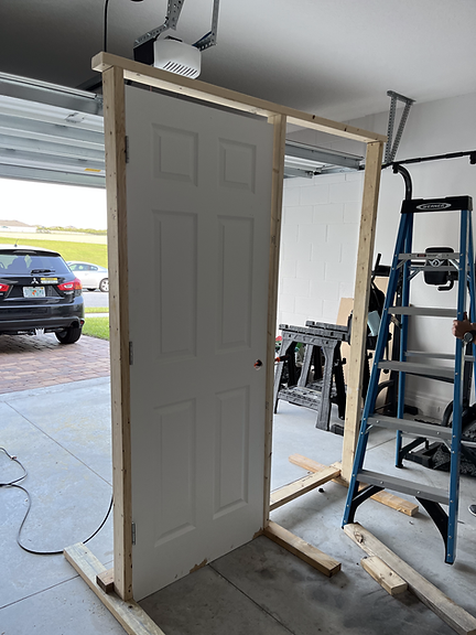

The above two photos show the frame pieced together with the door mounted. What is left is to continue to square up the structure as well as put up the wall. Some components are starting to come in so they will be installed as they come in.
Week 12: 7/24 - 7/30
In the twelfth week:
Jon
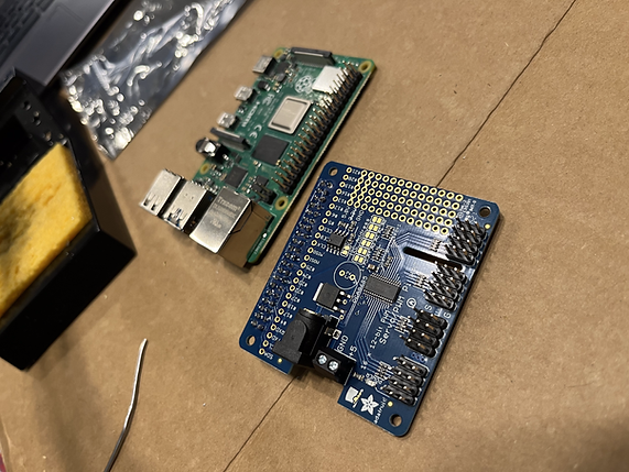
Assembled the servo shield and soldered all the joints. Attached it to the Raspberry Pi to check for physical connectivity. Checked all soldered joints with a multimeter to make sure no shorts were accidentally created while soldering.


The above photos show what the servo hat looks like prior to being assembled and soldered.
Servo hat assembled and soldered.
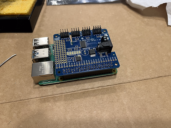
Servo hat assembled and mounted on top of the Raspberry Pi
Checking the servo hat with a multimeter for shorts.
Jon continued to work on the website. Jon made edited the Design Engineering Requirements and Design Engineering Specification.
Charlie
Installed the operating system on the Raspberry Pi. Updated the report charts, hyperlinks, table of contents.

Week 11: 7/17 - 7/23
In the eleventh week:
Jon
Ordered and received one of the two Raspberry Pis as well as the servo shield. Continued to order parts for the design phase of the project.
Charlie
Waited for one of the two Raspberry Pis to arrive.

Week 10: 7/10 - 7/16
In the tenth week:
Jon
Made a change of a component of the servo hat needed for the servos. After our Senior Proposal Presentation, one of the panelist had noticed that we had selected a servo hat for Arduino and not for the Raspberry Pi. The Adafruit 16-Channel PWM/Servo HAT & Bonnet for the Raspberry Pi will need to be used in order for the GPIO's on the Raspberry Pi to connect correctly. The following images show the schematic for the HAT for the Arduino and the HAT for the Raspberry Pi. The power supply we have selected for the previously selected HAT will still work for the new HAT. The Servo HAT was ordered as well as both of the Raspberry Pis.

Adafruit schematic for Arduino servo shield

Adafruit schematic for Raspberry Pi servo shield

Input voltage landing site for the Raspberry Pi Servo Hat will work with the power supply selected for use.
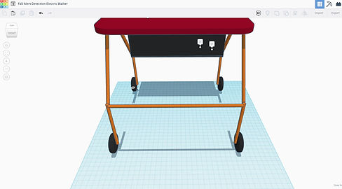
A 3D mock up was also created to provide a visual representation on what needs to be built in order to test and implement the H.S.E.S.


Charlie
Modified the numbered weeks for the project timeline as suggested by Professor Notash. He also ordered one of the two Raspberry Pis.
Week 9: 7/3 - 7/9
In the ninth week:
Jon
Redid the block diagram for the H.S.E.S. The changes done to the block diagram include moving the blocks around so that they flow better and are easier to follow. The color of the blocks were also changed.
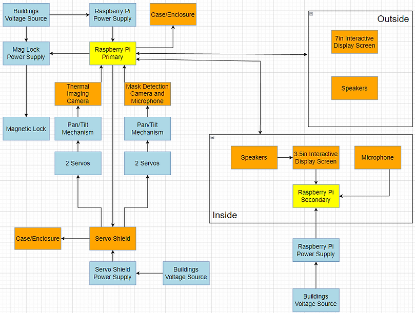
Jon redid the main Flowchart and Block Diagram.
Charlie
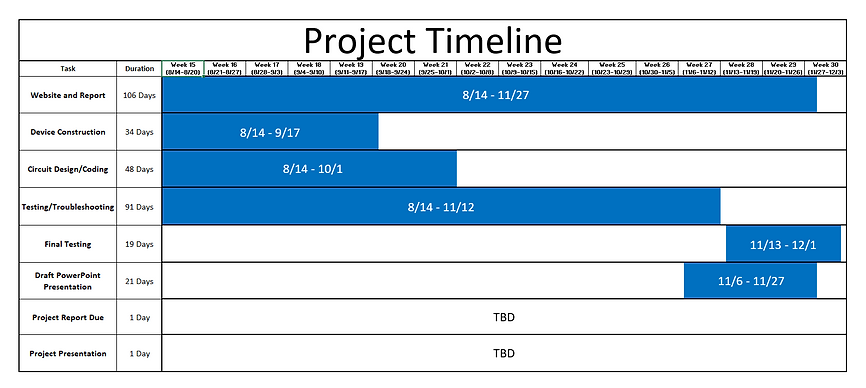
Redid the Proposal Timeline and Project Timeline with more accurate dates provided by Professor Notash. He continued working on the report and included descriptions for the block diagrams that Jon redesigned.


Group
Charlie and Jon worked on rewriting and updating the Proposal. The new changes include personal items such as speakers,microphones and the door as well as the lumber needed to build the structure. This structure will be our mock up of a point of entry for a medical facility.

Charlie and Jon presented their Senior Proposal Presentation to Valencia College faculty and the engineering panelist. The feedback received from the panelist is as follows:
Week 8: 6/26 - 7/2
In the eighth week:
Jon
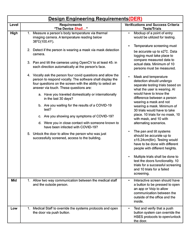
Jon continued to make the changes needed on the website. The Design Engineering Requirements was rewritten to sound concise, clear and straight to the point. The DER needed more specifics for the camera system as well as the COVID-19 questionnaire system. The photo below is the most updated/recent DER.
Jon also drilled and assembled Charlie's 3D printed model of the Pan and Tilt system. This was printed to possibly do a proof of concept utilizes this piece of equipment.


Charlie
Week 7: 6/19 - 6/25
In the seventh week:
Jon
Jon celebrated his first Father's Day and then later spent an entire day in the ER to take care of his son.
Jon made more updates to the CAD drawings to reflect the new changes. These changes include removing the vertical structure and replacing it with cameras that pan and tilt. This allows the cameras to move independently and simplifies the goal of having the cameras move and look at an individual. Also, the orientation of the cameras and touch pad were changed. They should be mounted to the opposite side of the door so that when the door is opened, it does not hit anything that is part of the system. The touch screen is setup in a manner where it does not move with the cameras. Jon also modified the HSES Financial Budget.
Charlie
Charlie updated the Proposed timeline and weekly timeline. These were both uploaded to the website. He attempted to 3D print a camera module housing for the purpose of having a tilting mechanism. He then updated the Success Criteria based on the new parts required for the tilting camera system.
Group
As a group, we performed research on how pan and tilt systems work with the Raspberry Pi. We needed to make sure that the Raspberry Pi can control at least four servers, so the Adafruit 16-Channel PWM hat stepper motor controller was added to the project instead of using the A4988 Stepper Motor Driver. The Raspberry Pi does not do PWM well so the use of a external motor controller is needed. We continued to work on adding material to the website as well as working on the Proposal Report.
Week 6: 6/12 - 6/18

In the sixth week:
Jon
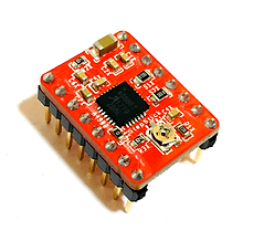
Wrote out the Design Engineering Requirements, Abstract and Description for the HSES. He did research on FLIR and mask detection systems as well as stepper motors and how to control them to obtain a specific degrees. Using a A4988 Stepper Motor Driver and a NEMA17 motor was considered as the driver for the stepper motor. Since the stepper motor would have to rotate a some what heavy load, driver would need to handle enough current to be able to move the weight up and down.
The above photo shows what the A4988 Stepper Motor Driver looks like. This drive could control up to four coils of a motor. It operates at 5V from the controller and has a max output capacity of 35V at 2Amps. The main reason why this was considered is because it can control stepper motors in full, half, quarter, eight, and sixteenth step modes. This is important when considering the accuracy of the height that we needed the cameras to be at. The smaller the step, the more accurate of a movement the stepper motor can make.
This LINK here will show an example of a Raspberry Pi utilizing this driver.
Jon also made updates to the previous CAD drawings which incorporated the camera pan and tilt changes that were later approved by Professor Notash. The new CAD drawings also included more realistic dimensions as well as a door location change as suggested by Professor Notash. Jon also created the Proposal Budget and Proposal Power Budget.
Charlie
Added dimensions to the FADEW diagrams as suggested by Professor Notash and updated the components inside the components box. The FADEW diagrams were again updated to show the new location of the components box. He wrote out the HSES success criteria based on the Estimated Budget Spreadsheet created by Jon. After watching some YouTube tutorials, Charlie was able to create a Gannt Chart of the Proposed Timeline on Excel; this was then uploaded to the website. The website was also updated to replace the FADEW from the homepage with the HSES.
Group
Charlie and Jon looked over the Design Engineering Requirements for both FADEW and HSES to ensure everything from the list provided by Professor Notash was included. They both continued to do research on temperature tracking systems and mask detection systems. Both continued to update each other via texts and phone call on tasks performed and tasks needed to be completed.
Week 5: 6/5 - 6/11

In the fifth week:
Jon
Performed research on LevoUSA, a company that makes wheelchairs that also allow a person to stand. This research was done to find examples of similar project to the Fall Alert Detection Electric Walker (FADEW). He also did research on hub drive and mid drive motors and how they are controlled.
Jon downloaded and experimented with TinkerCAD as a potential software alternative to FreeCAD to create 3D CAD drawings. After receiving feedback from Professor Notash, Jon modified the PDFs with the necessary changes that were wanted. The changes include a two-way communication/interaction between inside personnel and outside individuals (patients, visitors, etc); This would assist the individuals in case of difficulty and all other matters such as postal or other commercial deliveries requiring access and more.
Charlie
Watched tutorial videos on TensorFlow 2.0 and how to use Python to create facial detection systems.
Charlie downloaded and experimented with TinkerCAD as suggested by Jon. He began a rough model of the Fall Alert Detection Electric Walker (FADEW).
Group
Jon and Charlie worked collectively, during a call, to write out a detailed report on the functionality of the Fall Alert Detection Electric Walker. This was a more elaborate document that included the seven aspects that the professor was looking for in each of the ideas.
Week 4: 5/29 - 6/4
In the fourth week:
Jon
Updated the Draw.io files to make the suggested changes from Professor Notash. This included formatting the block diagrams and flowcharts to make them more legible. He updated the PowerPoint presentation to include the new block diagrams and flowcharts as well as the rough estimates for the budgets. Jon called the City of Haines City Water Department to set up an appointment with the Chief Operation Lead for Haines City Water. He created a design sketch for the Health Screening System and did research on elevator systems and conveyor systems to see how they could be implemented into the project.
Charlie
Charlie created a design sketch for the Electric Walker idea. He continued watching more tutorials on how to use FreeCAD software in order to be able to create sample designs. He also watched tutorials on how to used dynamic pages on Wix. On the website, he updated the Weekly Minutes with Professor, the Progress Log for weeks one through four, and the Proposed Ideas page. For the Proposed Ideas page, he updated the block diagrams and flowcharts to be larger and more legible, included the group member skills for each idea, updated the budgets for each idea, and included websites for similar systems.
Group
During a call, the group discussed how each project should function and how they should look. This was done to have a better visualization of what each of the group members expected the three ideas to look like. The group later determined what needed to be changed with the group dynamic. This included a discussion on how best to talked the upcoming tasks and deadlines for Tuesday as well as how the group needs to spend more time working collaboratively. Working independently slowed down the process since the group members had to wait for each other's response before moving on with an idea. Working independently also cause some confusion in which resulted in having an Advisor Minutes page and Weekly Minutes with Professor page. As suggested by Professor Notash, the group wrote out a detailed report on the functionality of the Health Screening Entry System that followed the seven requirements to be included in each of the three proposed ideas.
Jon and Charlie did research on mask recognition and on thermal imaging. This includes applicability, brief history, and functionality. The following links are a some of the things viewed.
KINTRONICS Thermal Body Temperature Screen Cameras
https://www.youtube.com/watch?v=EoDFUQsUeN4


The design above shows a drawing of the idea for the Fall Alert Walker. Below the seat of the walker, there is a platform where the battery and Raspberry Pi 4 are placed. The wires coming from the Raspberry Pi 4 are connected to the sensor on the top bar of the walker. This sensor is an accelerometer that will be used to determine if a fall has occurred. The diagram on the right show the general dimensions of a typical walker. This particular model include a basket under the seat. This basket may be modified to house the components.

This is a diagram of the Health Screening Entry System. The system shows the standard dimensions for a door. This front view of the door shows that the device will be installed in both the door and three feet from the door. In the door, there is a deadbolt that is controlled by a motor. This motor is connected via a wire to the components, which contains the Raspberry Pi 4, motor shield and power supply. The ultrasonic sensor will utilize a pulley system with a motor to adjust the height of the device based on the individuals that step on the yellow dot. This yellow dot indicates a three feet distance from the door. Given all the right conditions, the door should unlock and open for the individual that is scanned.
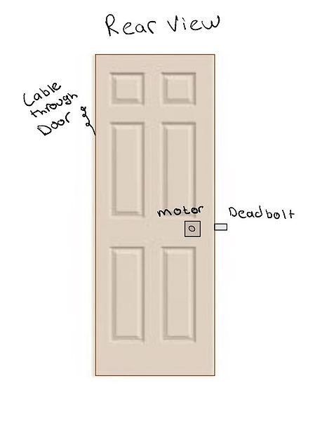
This diagram is the rear side of the door and indicates the cable wires that from from the components box to the motor and deadbolt combination.
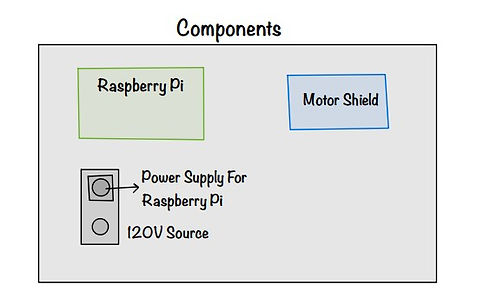
Inside the previously mention component box is a Raspberry Pi 4 Model B along with a Motor Shield and Power Supply. Due to the current needed by the motorized deadbolt, a 120V source will be used.
Week 3: 5/22 - 5/28
In the third week:
Jon
Worked on the PowerPoint presentation for the next meeting. He performed research on battery cells, electric motors, arduino LTE capabilities and walkers. He spent some time learning how to use FreeCAD in an attempt to make a simple model of one of the project ideas. He made block diagrams and flowcharts for the Health Screening Entry System. He edited the current break down of the electric walker idea and elaborated on its tilt/fall capabilities. He created a general budget list for the electric walker. Jon continued editing the website to ensure that it followed the guidelines of the rubric. This included the Time and Effort page and the Advisor Minutes Page.
Charlie
Researched microcontrollers and microprocessors such as the Arduino UNO Wifi Rev2 and the Raspberry Pi 4 Model B. He added some items and created an estimated budget required for the Watercraft idea. He updated the block diagrams for the electric walker and gesture controlled RC car. He organized the website and PowerPoint presentation by continuing to add more information to different pages in the Senior Design Proposal section. Charlie also created a list of items for the group members to take care of to distribute the work load.
Group
During a video call, the group discussed the possible body design of the Watercraft idea. Charlie worked on a rough CAD drawing for the water craft and the both of them performed a rough budget analysis for the idea based on an airboat. The group looked over the materials to be completed by the 4th week. This included website changes, creating drawings for the project ideas and PowerPoint presentation.

This is a simple model of the Watercraft inspired by an airboat design. The small box shown behind the circular disk contains the components needed for the project. This includes the Raspberry Pi 4 as well as the power supply.
Week 2: 5/15 - 5/21
In the second week:
Jon
Organized the files in the shared Google Drive so that they were easy to access. Jon also created the Project Idea page on Wix, which included writing a paragraph description of the ideas as well as their functionalities. Research was done to show similar project ideas that already exist. These can be seen by the hyperlinked texts.
Charlie
Continued to work on the Block Diagrams and Flowcharts and added them to the PowerPoint presentations as was required by Professor Notash. Charlie researched potential items that could be used interchangeably between the project ideas to determine possible sources where they could be purchased and to get a rough estimate of the cost of items.
Group
During a few calls, the group worked together to develop the Block Diagrams and Flowcharts. The group performed research on the types of sensors that may be needed for each project as well as determining if microcontrollers or microprocessors will be used. The research also included an elaboration of the ideas to provide detailed descriptions and functionality of the RC Watercraft.
Week 1: 5/9 - 5/14
In the first week:
Jon
Wrote out detailed descriptions about the proposed project ideas. He also did research on what software to use for block diagrams and flowcharts. He started to develop block diagrams and flow charts for ideas. He did research on how specific aspects of the project should be implemented so that it can properly be added to the block diagrams and flowcharts.
Charlie
Put together the Powerpoint for the first meeting with Professor Notash. He created a Google Account for the group so that sharing documents and any files made would be easier. This same Google Account was used to create a Wix account to start the group website. With Wix, he created a general template for the group to follow. Charlie found a software called Draw.io which he used to create the block diagrams and flowcharts.
Group
Together, Jon and Charlie went over ideas and propositions. In their first meeting with the professor, the group learned about the requirements for the class as well as expectations from the group. After meeting with the professor, the group looked over website layouts created by former and current students and discussed the criteria that must be met for the PowerPoint presentations. This included splitting the work for making the block diagrams and flowcharts. During a call, Charlie and Jon discussed how each of the ideas should be implemented.
Pre-Semester Work
Charlie and Jon met for the first time one week prior to the start of the semester to brainstorm some ideas. Below are some of the initial project ideas.

bottom of page