top of page

Progress Log
Week 30: 11/27- 12/3
Group
Charlie and Jon worked on the final PowerPoint Presentation that would be presented to the panelists on December 2nd.
This marks the end of their Senior Design Project.
Week 29: 11/20- 11/26
Group
Charlie and Jon worked diligently to complete the final report.
Week 28: 11/13- 11/19
Group
Charlie and Jon recorded more videos to show different variations of what would happen with the system. Charlie also brought his girlfriend who was unfamiliar with how the entire system worked; the group wanted to see how an individual who was unfamiliar with the system interacted with it.
The video below shows that a popup window appears when a person is not wearing a mask. Charlie's girlfriend demonstrates that when you click "OK", the popup window disappears as long as the person is wearing a mask. When the mask is removed, the popup window reappears informing the person that no mask is detected.
The video below shows that a popup window appears when a person is not wearing a mask. In this scenario, Charlie's girlfriend is wearing a mask, so there is no popup window with no warning. Charlie then appears in the field of view of the camera with no mask on thus triggering the popup window to appear. when Charlie clicks "OK", the popup window reappears because the system is still detecting him without a mask on. This shows that the system works well with only one person at a time.
To prove that the system works with both males and females, Charlie's girlfriend demonstrates the entire process for entering the building when all the required conditions are met. She also demonstrates the process for exiting the building by simply pressing on the "Door Exit" button to unlock the door.
To simulate a fever, Jon places a hot towel on his forehead so that the Pimoroni camera detects a temperature that is too high to enter the building. In this scenario, a temperature that is too high triggers a popup window to appear informing the person that their temperature is too high and to contact the front desk.
This is another demonstration showing that the system works successfully for an individual that is wearing a mask, hat and glasses. Jon is also demonstrating that the magnetic lock will always relock after 5 seconds of being unlocked.
In this scenario, Jon meets all of the physically visible requirements needed to enter the building: wearing a mask and having the appropriate temperature. However, he answers "Yes" to the question "Are you showing symptoms of Covid-19?", which prevents the door from unlocking. This aspect of the system is important because there will be symptoms that the mask detection camera and thermal camera will be unable to detect, i.e., no sense of smell and no sense of taste. Some individuals experience mild symptoms of Covid-19 and may not even realize they have it. The questionnaire can really only be successful based on honest answers by individuals. This is regardless of it being digital or non-digital.
A previous problem that the team was having was the audio playing over each other when the questions were answered quickly. This was mitigated by modifying the code to make the audio files global variables that are played for as long as their respective question appears.
Many people have experienced their mask breaking through no fault of their own. Most facilities provide a customers and patients a new mask as a courtesy. In this scenario, Charlie has a broken mask, but requires access to the building to obtain a new mask. To do this, he first makes a call to the personnel inside the building. Jon, the personnel, is then able to unlock the door with the "Open Door" button on the 3.5" touchscreen display at the front office desk. The door is able to be unlocked, which prevents the need of Charlie answering any of the questions. Facilities in this scenario would then proceed on what to do further after this point.
This scenario repeats a demonstration of what happens when a non-patient needs to enter a building. In this instance, Charlie is a delivery person who needs to enter the building to deliver a package. Because he is a non-patient, he is not required to answer any of the Covid-19 questions. He then initiates a call to the personnel inside the building who manually override the system by unlocking the door remotely from inside the building.
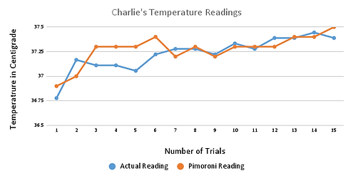
Professor Notash wanted us to measure our temperature with the multiplier with the thermal imaging camera as close to our foreheads as possible. Leaving the multiplier as it was, we measured four different peoples temperature, one set from the TIC and another using the forehead thermometer. Each person did 20 trials, with a total of 40 trials for each person. These people are Jon, Charlie, Liz(Jon's Sister), and Susana(Jon's Wife).


What is concluded from this analysis is that when we were as close as possible to the TIC, percentage error increased with each temperature reading. Essentially, by getting closer we got worse results. Since the multiplier that we added to the code to calibrate the effectiveness of the TIC, this number was proportional to the distance of 2.5ft since the very first temperature reading was done at 2.5ft. Hence, having use that multiplier at a distance of "close as possible", it proved not to be nearly as effective at measuring temperature when compared at 2.5ft. Though the numbers are still within a 5% range of error which is better then the percentages we were getting in week 25, these are not the results we were hoping for. With the calculated multiplier, it is more effective to measure a users temperature at 2.5ft than at any other distance. This kept our accuracy of temperature readings within 1%. This help prove that we do not want to move the TIC(Since this was first originally thought of to mitigate our temperature issue) from the position where it is currently.
Week 27: 11/6-11/12
Jon
Jon continued with data analysis of the different temperature readings. This includes creating tables of each individual testing with two types of test being done. One test was measuring body temperature with the physical forehead thermometer and the other was measuring body temperature using the TIC. This data was compared and graphs were made.
Charlie
Continued editing and updating the website. Using the data tables that Jon put together, Charlie organized them within the shared Google Drive to fit within the website.
Group
Jon and Charlie took Professor Notash's suggestion about informing the user of a high temperature, so that they understand why the door will not unlock for them. Charlie and Jon took this a step further and decided to do the same for the mask detection. When a person walks up to the health screening system without a mask on the touch screen will prompt them with a pop up window that displays "No mask detected". This pop up will continue to show and prevent the user from answering the Covid-19 Questions until a mask is put on. The same feature is set for high temperatures; when a person walks up to the health screening system, and they have a high temperature, the touch screen will prompt them with a pop up window that displays "The system is detecting your temperature to be elevated. Please contact staff." In either case the person is able to use the "Call Button" to contact the front desk staff for assistance. In that scenario, the front desk staff will proceed with the correct protocols set for them by the facility; i.e give the person a mask or manually scan their temperature.
The video below shows the pop up window prompt that will appear when a person is detected to not be wearing a mask.
The video below shows the pop up window prompt that will appear when a person is detected to have a temperature that is elevated.
In order to try and mitigate the temperature reading issue we had found a few weeks ago, we needed to continue with more test with the TIC. We realized that the TIC was reading temperature much lower than what is acceptable. For example, when the Charlies TIC temperature and actual temperature was compared for accuracy, it was found that it was inaccurate up to 10% at times. This is deemed unacceptable. Charlie had the idea of 'calibrating' the TIC so that the difference between the actual measurement and the measurement from the TIC can be minimalized. If we can find a numerical value that can be multiplied to the input temperature of the TIC, then maybe we can reduce this difference of inaccuracy. Starting with Charlies smallest percent error, we took that value and multiplied it to the readings coming from the TIC. The following tables and charts reflect this value.
The smallest number garnered from the first set of testing from Charlies measurements was 7.82% So we decided to round up to 7.9 and use this as a multiplier.

Here we can see the edit in the code. The np.max(data_array), is our input of our temperature. This is the highest seen temperature that is being measured by the TIC. We take that value and we multiply it by 1.079.
The following data measurements are from Charlie, Jon, and Liz. Liz is Jons sister. This was at the 2.5ft mark away from the "wall" with the garage door closed. The garage door is acting as a back drop for the camera.


Looking at the above data we can see by adding the multiplier to the code, that it made up the difference in temperature that was otherwise reading low. This is compared to the previous data from week 25. The data garnered brings the percent error lower than one percent for each person which makes it acceptable for what we were looking for in regards to the DER.
Week 26: 10/30 - 11/5
Group
Most of the work done this week was group work. We got together to continue to work on the communication between the outside Raspberry Pi and the inside Raspberry Pi. We were able to incorporate the communication to the remote access GUI that was developed for the inside Raspberry Pi. A call can be initiated and ended.

The above video shows Charlie and Jon utilizing the voice communication system between the two Raspberry Pis. Jon plays the roll of an employee inside the facility and Charlie plays the roll of a courier.
This video here shows Charlie with a duckbill style N-95 mask. This is an example of how we performed some of the testing to check for proper functionality and issues. Charlie repeated this process multiple times with different types of masks.
Here is another video showing Charlie testing the system with a blue mask instead. Multiple tests were done with different set ups in regards to head wear, glasses, no glasses, different color masks, hair up and hair down.
Week 25: 10/23 - 10/29
Jon
Jon had started to troubleshoot and diagnose the issues with the pan and tilt system. The camera system from home had no problem panning left and right but had an issue tilting up and down. The system would tilt down and not back up. This led to investigating a possible torque issue. This took some significant time of diagnosing and fixing.
Upon visually inspecting the Y-axis servo motor, it was seen that the inside drive gear teeth were stripped and was simply just spinning. Because of this, there was no possibility that the camera could be lifted. With the short amount of time we had, we could not purchase servos that produced more torque. The servos used are made out of plastic including the drive system.
Because of this, some weight needed to come off of the mask detection camera.

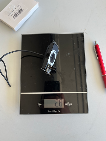

The mask detection camera with the thermal imaging camera weighed for a total of 87 grams. Once we took a portion of the camera apart, the camera weighed just 28 grams. With the removal of 59 grams of weight, the pan and tilt can be tested. The Y-axis servo was replaced with a new servo that had previously been tested for functionality


The corner of the Y-axis was trimmed so that it has more clearance while rotating. With software edits, the X and Y axis was determined.
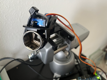
The camera was mounted to the pan and tilt with velcro. This proved to be effective since this is 3M velcro.


The photo on the left shows the camera at its minimum looking down and the photo on the right shows its maximum looking up.


These two videos show the pan and tilt cameras working as they should. They show the camera tracking jons face. This occurs with or without a mask.
Jon also worked on and finished the GUI for the indoor Raspberry Pi. This program utilizes Tkinter for the GUi and pigpio and GPIOzero for accessing the outside Raspberry Pi remotely. This took time to figure out because the router was blocking the signal going out.
The next thing was to try using the indoor Raspberry Pi to access the outdoor Raspberry Pi. A jumper wire was connected to GPIO 21 of the indoor Raspberry Pi to a red LED on a bread board. The goal here was to try and get this LED to flash while running a python script from outdoor raspberry pi. This proved to be successful with no issues. Once this was done, I tried again to access the outdoors GPIOs. The goal here was to open the door remotely from the indoor system. The script written still did not work.
After spending time diagnosing it was determined that the 3.3v signal coming off of the outdoor GPIO 21 was connected to the wrong spot on the bread board in the electronics enclosure. Once this was rectified, the script written worked flawless. Once it was determined that it would work every time, a GUI was developed to allow a push button.
The above video shows Jon demonstrating how the GUI works.
The temperature system, works, Covid questionnaire works, mask detection works, and facial tracking works but for some reason, they do not work all together. At the time this was a work in progress. When Charlie and Jon got together this problem was rectified.
Charlie
When Charlie and Jon attempted to do a video recording for the voice communication system, it failed to work. After troubleshooting the existing code several times, Charlie decided to look for alternatives. The video below is an example of a Walkie Talkie style of communication using Raspberry Pis. The problem with this solution was having to create and maintain a mumble account to use as a server. The code would also take a long time to modify to work with the existing GUI for digital control as opposed to physical controls.
Charlie created a Twilio account for the purpose of using it for voice communication. There were issues when setting up the account and applying for the trial period. This method would not be feasible because it would have to be maintained monetarily.

Another option would have been to use parole, which did not require a subscription service. It is a VOIP program that would allow making calls from the terminal. The difficulty about implementing this on the current system is that the language is in C and not Python. This would have been more challenging adding to the GUI of both the indoor and outdoor Raspberry Pis.

To make matters worse, the 128GB SD card that Charlie was using for the Raspberry Pi 3 became corrupt. This resulted in having to reinstall the entire operating system again onto a 64GB Samsung EVO SD card. Once this was up and running on the Raspberry Pi3, Charlie reinstalled all the necessary libraries for the communication portion of the system; this included reinstalling vidstream, which was the original choice for the team that stopped working.

Using the original working code that was used, Charlie was able to get the voice communication system running again. With the help of Khon some modifications in the 'receiver.start_server()' and 'sender.stop_stream()' were created to add functionality to the "End Call" button on the GUI.


The following videos below are Charlie's demonstrations of the voice communication system.
Group
We got together and did lots of troubleshooting and diagnosing of the problem we had of the main program not working. We had assumed that the issue was with one of the libraries so we had to completely reinstall Open CV and TensorFlow. Even though these libraries were reinstalled, this did not fix the issue. After hours of going through our code and comparing it to older code, we eventually found the issue and it had to do with an accidental misspelling . The spelling issue was locking up the threads, preventing the program from running completely. Once this was fixed, we were able to commence with testing of our system.
At the time, Charlie was still working on the voice communication, we tried to give the inside Raspberry Pi a static IP assuming that this the issue preventing the voice communication from working. For some reason, upon trying to change the IP, the WiFi stopped working on the inside Raspberry Pi. The WiFi driver files ended up corrupted for some reason and needed to be reinstalled. We decided to just copy the OS image from the working Raspberry Pi and copy it over verbatim. This actually helped with testing because both Raspberry Pi's had the same exact libraries. Once the OS was reinstalled, everything worked as it should. We continued with testing of the whole system.
After the GUI was created to open the door from the inside, an issue developed with the main program code. Where the RPi.GPIO library was not working. So when we would run the main script, it would work as it should but the door would not open. After trouble shooting we determined that the portion of the code that opened the door had shifted around(which probably happened by mistake), causing the door not to open. We rewrote the code the way it should be written and the system is back to working as it should. We continued to do testing and recordings of the system.
The following videos are of us testing the system. This includes Charlie and Jon using different color and types of masks. Jons sister also helped out to see how the system would work with a female participant with long hair. The video does not reflect all of the testing but each run through was done at least 10 times each.

The above video is of Charlie testing the push button exit switch for "leaving" the doctors office.


This video shows Charlie going through the entire process of the system wearing a blue mask.
A video showing Charlie with a pink N-95 'duck bill' style mask.

This is a video shows Jon in a tank top with a black hat, long beard, and a pink n95 mask.


The above video shows Jon in a tank top with a black hat, long beard, and a typical blue mask.
Here Jon is recording him self recording the camera tracking his face. On the monitor to the right of him, yoiu can see a green square around his face in the video feed. This indicates that the system recognizes that he is wearing a mask.

Here is Jons sister using the system. She participated using a blue mask through multiple tests of going through the system. We wanted to test the system on recognizing a person of the opposite sex and with someone with long hair. She is wearing a typical blue mask.
A couple of weeks ago, we had addressed an issue where we needed to add a backdrop because the thermal imaging camera would not work when it was really hot out. The issue was the thermal imaging camera was picking up lots of hot ambient temperatures in the back ground, not allowing the person trying to enter, to enter. This was rectified by hanging a sheet in the background in the field of view of the cameras. All the testing done during the day was with the garage door open, utilizing the sheet.


Here is Jon testing the system with a blue mask but the recording is coming from his cellphone as if it is a first person view.
We were able to garner some data as well. We did find out our thermal imaging camera is not working as intended. We first tested our forehead temperatures with a roll on skin type thermometer. The one we usesd is pictured below.


Using this thermometer, we compared our numbers to readings from our face utilizing the thermal imaging camera. To do this, we placed our face one foot away from the thermal imaging camera. The TIC works by taking the hottest temperature in its field of view. So the closer you are, the more accurate of a reading. The readings were then written down into a table.

The above table is all the data garnered from this test. A total of twenty trials was done per person. Ten measurements with the hand held thermometer and ten done with the TIC.
Looking at the table, we can see that the percentage error is greater than the two percenter we were going for.


The above graphs show the temperature changes over the span of the 10 trials each. The drastic difference in the temperature readings poses a problem. When you run through the program, simulating a patient/user, the system is reading your temperature. Anything over 38C is not allowed in. This was tested with having something very hot in view of the TIC. What was used was a small propane torch. When the torch was lit, the system would not open the door. The issue here is that with the eight to ten percent of error, if you have a fever at 38C, the TIC will read your temperature much lower then what it actually is. Thus, giving you access since you "do not have a fever". Further testing is going to take place with positioning the person getting read in regards to where the TIC.
Week 24: 10/16 - 10/22
Jon
Worked on the audio aspect of the GUI. Now going through the questionnaire the audio from the previous question statement stops before playing the next audio clip. The issue here was with out this feature, the audio would walk all over the place. If you went through the questionnaire quickly, the audio from the previous window would continue to play even though the new audio is playing. This made a mess with the audio and needed to be fixed.
Started to work on the GUI for the Indoor Raspberry Pi.
Charlie
With the help of Khon through voice chat, Charlie was able to add Jon's functioning servos to the mask detection file. The code below shows the additional lines that were added with the purpose of keeping a single person centered in the window.

Below is a video demonstration of the pan and tilt mechanism tracking Charlie. The video still shows that he is not wearing a mask, but the camera is still attempting to keep him centered in the window.
Due to the unforeseen size of the pins for the Raspberry Pi hat, the cables that were installed became too high. This prevented the Raspberry Pi case for the 7 inch screen from closing. To mitigate this issue, Charlie created an extension for the back of the Raspberry Pi. This was designed in TinkerCAD and then 3D printed.

The image below shows the back of the Raspberry Pi 7 inch display. Due to the servo hat, the pins sit much higher, raising all of the connections for the thermal camera, fan, two servos, and relay.

Group
We added a 7" bracket to support the 7" display for tiltiing funcionality. This alow the user to move the screen manually if they need to. The phone was used as a leveling device.


Permanently mounted the outdoor Raspberry Pi unit to the bracket and connected the cables. The cables were routed through the wall and through the metal bracket.


The above photos show the 7 inch display, pan/tilt system, and both cameras mounted. All cables having been covered in wire loom. However this was temporary as replacement of parts and trouble shooting took place. The wire loom had to be taken off.


Here it can be seen Charlie sitting down and stand up on a chair. This was to show that different heights can still have access to the seven inch touch screen display. Not only that, they would have the ability to tilt the screen if they needed to. The photo on the left shows Charlie sitting at a height of just shy over 4" to the top of his head. The photo on the right shows Charlie standing a height of about 6'4" and still has access to the touch screen.
We had issues with the pan and tilt system and was not sure as to why. The camera had no problem tracking left and right(X-axis) but would not track up and down (Y-axis)Further troubleshooting and investigation is needed.
Week 23: 10/9 - 10/15
Jon
Worked on the GUI in the Open Lab. A disclaimer was added to the end of the questionnaire. This disclaimer is as follows "In accordance to healthcare mandates, masking is required for entrance into this facility during your stay. Do you agree to these terms?" The user must agree to these terms, if they do not, they are still not allowed entrance into the facility.


Start call and end call buttons were added to the same GUI as the questionnaire. This allows the ability to communicate to inside the facility. The End Call function is still a work in progress. The GUI will eventually be full screen and that is what the user will only see. Jon also made the harness that will run from the Raspberry Pi servo shield to the bread board that is mounted inside the electronics box. This will carry over the 5VDC, ground, and signal needed to control the relay to open and close the door. The GUI now plays audio for each part of the questionnaire. This includes asking all the questions out loud as well as the disclaimer. This did prove to be challenging but with the help of the VLC library for python, it made it possible. Using Googles Text-to-Speech software, we were able to get the questions in audio form. With this and some code, the audio was able to play. Now, every time a question is asked, it will play it out loud. It also will play the responses for both yes and no answers. A small description of what to do is also played in the beginning. Fix some issues pertaining to the audio. If you were to answer the questions to quickly, the audio would not stop playing and would simply continue playing even when the next question is played. This proved to be annoying and had to be fixed. With the help of the Open Lab on campus, we were able to define the audio files as global() variables and in doing so can stop and start playing when ever we choose.
Charlie
Currently, the webcam chosen for the mask detection has a field of view of 78°, which is sufficient for capturing people at various heights. This was tested previously with Charlie sitting on a stool, Charlie standing on the floor, and Charlie standing on a stool. Per Professor Notash's suggestions, a tilting mechanism should be implemented to pan and tilt up and down as well as left and right to accommodate various heights as well as patients with disabilities who are sitting on wheel chairs.
Charlie performed research, which included watching videos on object detection and servo motor tracking. The video below shows an example of what needed to be included in the mask detection code. When a person is detected, with or without a mask, the camera should recognize them and attempt to keep them in the center.
Group
The group got together to assemble the project to the door mock up. This includes both cameras, outdoor raspberry pi, all cable connections, and everything pertaining to the locking mechanism. Lots of testing as well as code modification also took place.


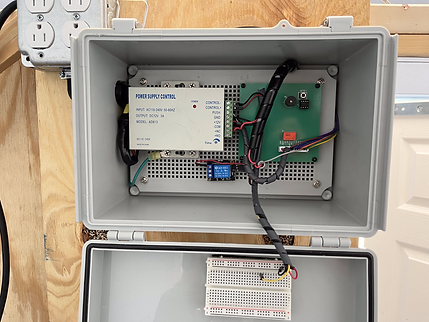
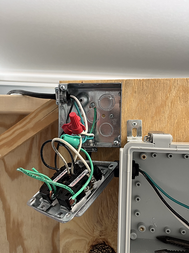
The components for the box on the wall were installed inside. Wires were pulled through the box as well. They come up from "inside" the wall and through the wall. This is ok since this is all low voltage cable. A bread board was also added to the inside of the door to the box. This is where the 5VDC, ground, and signals are going to be placed coming from the outside raspberry pi. The photo on the left shows the components installed and the photo on the right shows the same components installed but with all the wiring wrapped up neatly with wire loom. The manual exit push button as well as the door lock cable both come into this box. The harness to bring the 5VDC, ground, and signals will eventually come into this box as well. Until the Raspberry Pi is permanently mounted outside, the cable is going to just be hung over the wall. Eventually this will be installed permanently through the wall.

The above photo shows the harness made for the Raspberry Pi. Male end connectors were soldered to one end of the cable and female end connectors were soldered to the other end. The pins at the servo shield are female and the male connectors need to connect to the bread board mounted inside the box that houses the PSU for the lock. Color code was followed as well. Red cable is for 5VDC, black wire is for ground, and the yellow wire is for signal. All wires were sealed using heat shrink. Clear is what we had available.


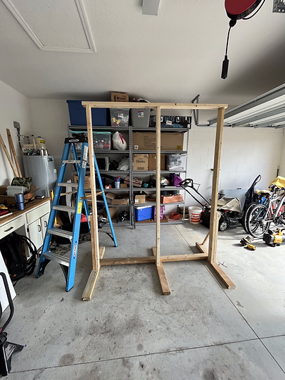
With left over wood, we decided to mount a piece to the outside of the wall. This will be the pedestal for the pan and tilt system as well as the raspberry pi and speaker. The camera needs to be mounted at a height of 48 inches(at the lens). The piece of one by mounted to the outside wall was placed at such a height to compensate for the 48 inch mark to be at the lens of the camera.
First testing done was with the thermal imaging camera. We wanted to see how the imaging was affected with having light and temperature differences in the background. We also wanted to determine if we needed a background because of this ambient influences.

The above image shows the thermal camera not being able to differentiate between the person standing in front of the camera and the background. Even though there is someone standing directly in front of the thermal imaging camara, the camera is focusing on the temperature in the background. Specifically the car parked directly behind the person. This was done to mimic a parking lot at the doctors office. This proves to be inaccurate because based on the temperature graph, the person in front of the camera temperature is 35 degrees centigrade or lower. If this was the case, the person would be in a state of hypothermia.

Here we see the TIC reading the temperature of said car. The max temperature being seen here is 46.5 degrees centigrade(115.7F)


Now looking through the lens of the mask detection camera, we can see that Jon and Charlie are not visible in the photos. They appear as merely silhouettes. This is due to how bright it is outside. With it being 1619 in the day, the sun was out; shining bright. This was all part in testing to see if a bright and hot background would affect the results and quality of the data input to the cameras. This proved that we need a backdrop for the cameras to accurately do what they need to do.


With Charlie standing in front of the camera and Jon improvising a backdrop using a children's pool, it is clear to see that it is easier to see the person standing in front of the camera with some sort of a background behind them.
With the photo above, it is seen that the mask detection camera can not only see Charlie but be able to distinguish between wearing a mask or not. Even with some of the background light still getting through, as long as the person standing in front of the mask detection camera is standing with a backdrop, it will still detect the person.

Since it has been proven that a backdrop is needed in order for these cameras to operate as intended, the garage door in the background was closed. The above photo shows Charlie standing in front of the TIC. All of these measurements are taking place at almost one meter away from the camera(3 feet).
The max temperature reading from the above graph is 35.2 degrees centigrade(95.36F). This is a low temperature given that the person in the camera is in a garage in the late afternoon in October. The original placement for a person to be scanned was at about a meter from the cameras. We needed to see if the accuracy of the TIC would increase if we got closer.


The above photos show Jon in front of the TIC(notice the glasses). As Jon got closer to the camera, the max temperature reading increased. The bottom most photo shows Jon at about one foot away from the TIC. The temperature being measured their is 36C. The accuracy of the TIC increased the closer Jon got to the camera. So from here on out we decreased the standing distance from the cameras from 3ft to 2.5ft. We cannot get any closer then this or the mask detection camera will have a hard time seeing the person standing in front of the wall.
The following videos will show the system working with some elements not working. The elements not work include the pan/tilt system as well as the voice recognition software to answer the questions. These elements are still a work in a progress with help from the open lab.
The videos shall have description as to what is going to be observed while watching the video. This will be seen below each video.
This video shows the system as is from start to finish. With Charlie performing the test, he begins by wearing a mask and starts to answer the questions. He answers no to all the questions and agrees to the disclaimer at the end. It is observed that the door unlocks when Charlie agrees to the disclaimer. Note, the thermal imaging camera is mounted to the mask detection camera. This was an approved design change from Professor Notash. The camera is small enough that it can be mounted to the mask detection camera with not issues pertaining to weight.
This video shows Charlie not wearing a mask and the system flagging him for not wearing it. He cannot open the door. He then puts a mask on but answers yes to the first question. The door still does not open.
Charlie answers yes to the first question but says no to the second. The door still does not open.
Charlie answers yes to the first and second question but answer no to the third. The door still does not open.
Charlie answer yes to all the questions with the exception of the disclaimer. He disagrees with the disclaimer. The door still does not open.
This video shows Jon testing the exit push button to open the door.
Week 22: 10/2 - 10/8
In the twenty-second week:
Jon
Jon continued to work on adding vocal features to the gui for the patients to use. This should allow the patients outside to listen to the questions being asked as well as be able to answer yes or no vocally.
First thing was to get familiar with voice recognition using python. Goal here was to turn on an LED with voice recognition. A video was used for help.
We needed to install the necessary packages in order to get the system to work.
pip install SpeechRecognition -- allows use of the speech recognition
pip install pyaudio -- lets the raspberry pi use a mic as an input
sudo apt-get install flac -- necessary codec needed that the raspberry pi doesnt come with

The above photos show that all the needed packages are installed already. The code written utilizes Googles Web Speech API for the speech recognition. The following video shows me using some garnered code implemented with previous code that I wrote for GPIOs to turn an led off and on.
The above video shows the speech recognition working with our equipment.
An edit was made to the outside GUI. The questionnaire is to end with a disclaimer stated that who ever enters the building must wear a mask at all times during the visit. This was a much better idea then just posting a sign at the front. The system will not allow entry unless they accept so this proves that it was read and the oolicy was accepted.


The above photos show the disclaimer as well as the two outputs depending on the input from the patient.
If the patient were to agree by selecting yes, the response is to "Please Proceed To Enter The Building". If the patient does not agree by selecting no, the response is to "Please Contact Front Desk Staff". The code runs in a loop so once the response is clicked on by selecting ok, the user will eventually have the ability to call the inside staff with a button.
Charlie
After a successful test communication between the two Raspberry Pis, Charlie repeated the process again with the Laptop to Raspberry Pi set up. He was able to establish a connection in the demonstration video below.
After ensuring the the voice communication continued to work with two different devices, Charlie began to add a GUI for the voice communication to add the ability to start and end the call. The original program was set to turn both speakers and mic on at start up. The diagram below shows the current version of the program that allows the call to be started with a "Start Call" button, but is unable to be stopped with the "End Call" button. Further investigation and tweaking of the code is needed.

The figure below is the GUI for the voice communication. The "Start call" button is currently working, but the "End call" button still needs to be fixed.

Group
The group got together for a significant amount of time on Saturday to work on the vocal portion of the project. The goal here was to:
1. Have the Raspberry PIs communicate through an ethernet cable
2. Verify that communication through WiFi is still an option as a back up
3. Be able to have a conversation with someone from one Raspberry PI to the other.
4. Incorporate a push to talk function in the existing GUI.
Using NeuralNine's video on VoiceChat as a guide.
NeuralNine created a python library named vidstream. This library makes it possible for this kind of communication through Python. We wanted to go this route instead of using a third party app like Mumble or something along those lines.


The photos above show us working and trouble shooting this process. First thing we did was connect one of the RPis to a laptop. This was tried using an IDE on the laptop. First thing to over come was to get the IP addresses. The Raspberry Pi did not want to show the IP address when connected via ethernet. We found a work around this by connecting the Raspberry Pi to the Wi-Fi and getting its IP then. Once we got the IP address of the laptop, we tried running the program. At first it did not work, we realized that if the WiFi antenna is turned on on the Raspberry Pi and its is connected via ethernet at the same time, it does not work. After shutting off the antenna, we tried again. At first the laptop only received voice but would not transmit voice. In short Charlie at the laptop was able to hear Jon speaking through the Raspberry Pi. This was mainly because of firewalls that Windows has. Something was not letting that through the laptop.
We then tried with both Raspberry Pis since this is how the system is truly going to be used. One of the Raspberry Pis utilized the mask detection cameras built in microphone as an input. Typical computer speakers were used as the output. The other Raspberry Pi used a plug in stand mic with a speaker connected via the 3.5mm audio jack.
When both sets of code are running simultaneously on both Raspberry Pi's, we were able to communicate with one another. This proved to be effective in the sense that there was no lag. We only sustained loads of feedback from one another but that is because we were in the same room.
The same test took place over WiFi as well. This proved to work but with some delay and lag in the audio response. It might of been because of where we are in the house in respect to the location of the access point. Either way this works and could be used as a back up if for what ever reason the ethernet connection does not work any more. The use of the ethernet cable keeps the systems off the network and keeps it secure from outside sources.
What is next is to add a push to talk feature in the GUI. This ability should be able to turn the mic off or on for both sides.
Week 21: 9/25 - 10/1
In the twenty-first week:
Jon
I started to lengthen the power cables that go to the Raspberry Pi and the servo shield that is to be mounted outside. What I did was take some left over 18/2 wire that I had and spliced it in line with the power cable. This was mainly done because the Raspberry Pi PSU came with a switch which made the cable bulky. Since the cable is going to be ran through the "wall", the switch needed to be eliminated in order to make a small hole in the wall.


The photo to the left Raspberry Pi PSU soldered together with another wire to extend the cable as well as to eliminate the in line switch it came with. The switch made the cable bulky. The photo on the right shows the cable done and assembled. It was connected to an old photo for testing. The phone powered up and started to charge the phone indicating that the cable works. I have been using the cable for the Raspberry Pi with no issues.
Charlie
Using the following video below, Charlie followed the tutorial on how to make a voice chat in Python. This program connected two devices together using their respective IP addresses. Because he only had one of the Raspberry Pis, Charlie used his laptop to attempt to establish communication between the two devices, but was unable to do so due to issues with the laptop connecting to the Raspberry Pi.
The following code below is of the Voice Call that is on the Laptop. The top IP Address is the IP Address of the laptop. The bottom IP Address is the IP Address of the Raspberry Pi. For privacy and security purposes, both IP Addresses have been marked out.

The following code below is of the Voice Call that is on the Raspberry Pi. The top IP Address is the IP Address of the Raspberry Pi. The bottom IP Address is the IP Address of the Laptop. For privacy and security purposes, both IP Addresses have been marked out.

Group
The group got together to continue to mount equipment to the door mock up. This includes varifying our 120VAC circuit works, installing the push to exit button, the 3D printed box for the push to exit button printed by Charlie, the magnetic lock, as well as the steel plate that mounts to the door.

First thing done was to add the 120VAC-15A plug to the cable end leaving the junction box. This junction box is where the equipment power will be connected and is there to simulate the building power that the HSES needs to get its power from. A plug was added so we can move the door mock up where ever we need to and still be able to connect it to a an extension cord.


With a multimeter, we tested our voltage at our junction box. This was done to both receptacles. While the junction box is plugged in, the image on the left shows that we are getting 121.5VAC when measuring neutral to hot. The image on the right shows the same voltage of 121.5VAC but it is being measured from hot to ground. In residential electrical, neutral and grounds eventually end up on the same connection at the main panel that is usually found indoors.


A measurement was taken between the top of the door and the bottom of the top of the door jamb to measure the gap. This gap was intentionally left so that if we needed to make modifications to the height of the door, we can do so with allowable play. The goal here is to fill this gap with a piece of wood so that the magnetic lock can be mounted flush with the top of the steel plate that will eventually get mounted to the door. A piece of 2x4 was cut to make up this difference.

The newly cut 2x4 was cut with a thickness of the difference between the top of the door and the bottom of the top of the door jamb. The length was cut to fit the inside width of the top of the door jamb. This measured at 74.93cm(29.5"). Once it was hammered in, it was secured with screws.
Next was to mounted the mounting plate for the magnet itself. This magnetic will bolt to this plate once the plate is installed. The plate was installed with screws and the hole for the wire was also drilled.


Here we mounted the magnetic lock and ran the wire through the top of the door jamb which is seen here coming out of the magnetic lock. The lock was put into place so that we may know exactly where the steel plate on the door needs to be mounted. Once we had our placement for the steel plate, we removed the magnetic lock so that we can continue bench testing.


The steel plate needed to be modified since the mounting holes on the outside were not completely drilled through. Since this was steel, a drill bit that is smaller than the holes diameter was used to drill through the plate first. Then, the actual size was used afterwards. This is what is called drilling a pilot hole. Using a smaller drill bit as a pilot is done for a couple of different reasons
1. Allows for a bigger drill bit to follow the path of the smaller drill bit.
2. Makes it easier to drill through thicker or harder material when there is already a hole.
We need both of these holes drilled through all the way to mount the plate properly to the door. Using only the center hole would cause the plate to rotate on its center and we wanted to avoid that. As seen on the image on the right, after drilling through the plate, a step bit was used to add a taper to the hole so that when mounting hardware is used, it will sit flush on the plate. Allowing no issues when closing.


Next to install was the push button exit switch. This was determined to be placed at a height of 121.95cm(48") . This seems to be a good height to be able to reach for a various different heights of people.

The image to the left shows what it would look like when the upper right most corner is at exactly 121.95cm(48") above the ground. The box mounted on the wall as seen on the image on the right was 3D printed by Charlie. His design incorporated removing mounting tabs as previously suggest and placing the mounting holes inside the box for a cleaner finish. This also prevents individuals from tampering with the hardware of the switch. Using the speed square as a level, it is seen that the box is nice and leveled with the ground.
The above video shows Charlie and Jon testing there system utilizing the magnetic lock and previously shown circuitry. Previously it was shown using LED lights but not it is actually connected to the magnetic lock.
Week 20: 9/18 - 9/24
In the twentieth week:
Jon
Goal for this week was to create a GUI for COVID-19 questionnaire. This was to be done using python as the coding language.
The above videos were watched and studied in order to create some sample GUIs. These video proved to be very helpful. Using this link also proved to be helpful.
The following photos show the first GUI made after watching the previously posted videos. At first, Spyder IDE was used to edit code. This proved to use to many resources to run so Sublime IDE was used.


The following photos show the clickable GUI that I was able to come up with. This was set up in a manner that one question was on one tab with the option of selection yes or no. If you selected no, it would tell you to "Proceed to the New Question". If yes is selected, the response is "Please Contact The Front Desk". This was repeated for all four of the questions. As exciting as it was to get this to finally work, this one does not work as well. You can go back and change the answers or just answer the last question as a no. This GUI was a start.


The above photos show the questionnaire asking the second question. They options to select are the same as question one. This was repeated through all four questions. This method did not work since I could not figure out how to get an output if all the answers to the four questions if they were answered with a yes.
The second program wrote seemed to work a lot better. It was more of a serial questionnaire rather then how it was set up previous. This proved to be more affective since a no would end the questionnaire with a response of "Please Contact Front Desk Staff."


The above photos show pictures of the second GUI that was developed. With this one being programmed with if/else statements, it worked a lot better for what we were trying to achieve.


Here we can see what is shown to the user when a response is selected. To the left, "Please Contact Front Desk Staff' is seen if any of the four questions are answered with a yes. Entry would then be permitted at the discretion of the medical staff. If the an no is selected, then the next question is prompted. You can only get to the final question if all the previously answered questions were answered with a no. When the last question is answered with a no, than the user is prompted with "Please Proceed To Enter The Building". The goal is that once this window is reached, the door is to unlock once all the other parameters are met,(temperature and mask detection).
Pan and Tilt Mechanism Testing
Testing was performed on the pan and tilt mechanism to make check for durability and longevity. This was done by mounting an equivalent weight to the pan and tilt mechanism and have the servos operate continuously over a period of time. Since I did not have the cameras with me, an equivalent weight needed to be used. Charlie took the weight of each of the cameras since I was not home. The mask detection camera weights 83 grams. The thermal imaging camera is so light that its weight did not show up on the scale.


Goal was to use something up to 20% of the weight of the device. I decided to just do the same weight for both pan/tilts mechanisms.

A socket weighing at 99 grams was selected. This was the closets small object that I could find that was small enough to mount to the pan/tilt as well as weighing almost 20% more weight. This was calculated using the following equation. ((W2-W1)/W1) * 100 = ((99-83)/83) * 100 = 19.2771%.

The socket was attached with a zip tie. This seemed to be suitable for testing purposes only. A program was written to cycle the pan and tilt system back and for on the x and y axis every three seconds for an hour. After inspecting the systems, non of the pan and tilt mechanisms showed anything gross and obvious in regards to damage or wear.
The only issue we had is that I had accidentally shorted out a servo by connecting it wrong. Additional servos were ordered to replace the one damaged one as well as to have extra on hand.
Charlie
With the help of Khon, a lab assistant in the Computer Science Department, Charlie was able to "combine" the information taken from the mask detection camera, thermal camera and CDC questions. The following code below is a portion of the code for the new Python file called "Unlock_Conditions" that was created to pull information from three different Python files using functions and custom dictionaries. The full code is available in the "Code" section of the website. Much more will need to be customized for the Graphical User Interface (GUI).

The video below shows all the requirements for the unlock conditions being met. Charlie is wearing a mask, the temperature is below 37.5 degrees Celsius, and all of the questions had an answer of "no". Once these conditions are met, a signal is sent to GPIO 21 that lights up the LEDs for 5 seconds. These LEDs are once again simulating the relay for the magnetic lock.
Unfortunately, while the current code works for meeting all the requirements, further tweaking is needed for the CDC Covid questions. In the video below, the temperature continues to be below 37.5 degrees Celsius, all questions are met with the answer "no", but Charlie is not wearing a mask. After all the questions are answered with "no", the display continues to have a popup window that tells the patient to enter the building, however, the GPIO does not actually send a signal to enable the LED lights. This means that the magnetic lock will not actually lock, but it will misinform the patient by telling them that they are able to enter. To fix this, the file with the CDC questions will also need to "pull" information from the mask detection camera and thermal camera or the popup for the "Please Proceed To Enter The Building" will need to be moved to the Unlock_Condtions file.
Group
Charlie took the weights of each of the cameras.

Here we see the mask detection camera measure at 83 grams of 2.93 oz.

The thermal imaging camera is so light that the scale is not sensitive enough to pick up its weight. These measurements were taken so that while the cameras are being used in development for the project, an equivalent mass can be used to attach to the pan/tilt mechanisms so that testing can occur. Goal here is to have the pan/tilt systems run for hours with the weight shown above. This is to depict if the cameras were mounted to the pan/tilt system. Jon will take care of the testing. The same amount of weight will be mounted to both pan/tilt systems for testing purposes.
Week 19: 9/11 - 9/17
In the nineteenth week:
Jon
Goal for this week was to get the servos to work. To be able to get them to pan and tilt. This was first done by getting the Raspberry Pi in a position to do so. Certain libraries and packages needed to be downloaded for the Adafruit Servo HAT to work. Adafruit is the manufacture of the HAT so with their help as well as core-electronics.com.au, we were able to figure out how to get the servos working.
First thing was to download the python-smbus; this is only needed if you have an older version of python. Even though we have a recent version, this was still tried.

The photo above shows us trying to install the python-smbus package. This did not work, as seen in the photo due to us having a recent version of Python which already comes with it.

We installed the i2c tools package as well. This was done earlier but a screenshot was not taken when the first initial install took place. i2c communication is not needed to control the servos, however, it was installed just incase we need to use it. What is i2c? I2c is a communication protocol used for serial communication. In this case it would be the communication between the HAT and the servos.

The final package to be downloaded and installed was created and developed by Adafruit, who is the manufacture of the Raspberry Pi HAT that is being used in this project. Their package was written in python and is needed in order to control servos using this servo controller. It had been installed earlier, which is wh it says no changes were made to the preexisting files.


The photos above show one of the pan and tilt mechanisms plugged into the HAT. The x-axis servo is connected to channel zero and the y-axis servo is connected to channel one. Utilizing help from the Adafruit website and core-electronics.com.au, I was able to write code to be able to pan and til for the full range of the servos. This can be seen in the following video.
The video shows the servos working back and forth. This was a on a continuous loop to actuate every three seconds. The following video shows all of the servos, both pan and tilt mechanisms, working in unison. They are temporarily screwed down to a cardboard box so that they do not move. This also was part of testing that continuously let this run for two hours. Every three seconds, all four servos would actuate to one extreme to the other. This was done non stop for two hours with no issues after the two hours were concluded. In this set up, the second pan/tilt mechanisms x-axis was connected to channel four and the y-axis was connected to channel five. This was done so that the pins were not so over crowded in the chance that trouble shooting needed to take place.
Charlie
Charlie created a simple window for the secondary Raspberry Pi that will be used for the employees indoors. Using a mouse, employees will be able to press the button labeled "Unlock Door" to unlock the door for non-patients who need to enter the building or for patients who need assistance unlocking the door.


The following code was commented out due to some output issues, but this is not essential to the functionality of the code.


The following video below is a demonstration of the functionality of the program. It is currently connected to three LEDs to represent the door unlocking. After five seconds, the LEDs turn off to indicate that the door is once again locked. When the group meets again, this code will be used to turn on the relay that will unlock the door.
Group
Charlie and Jon got together to continue to working on the door mock up. The 120VAC receptacle was wired in and finished.


The above photos show the 4 inch square box with a cable being ran into it. From the same 4 inch box a cable is going into our enclosure that is going to house our magnetic lock power supply. This is where the PSU will get its voltage from. The cable used was a 12 AWG computer wire that Jon had that he was not using. This was cut and integrated into the project.

The photo on the left shows the pig tails of the receptacles connected in parallel with the cables that were going into the 4 inch box. The photo on the right shows everything button up and closed. It may seem that the receptacles are upside down but in fact there is no such thing. The National Electric Code or the NEC does not require a specific orientation of the receptacles. This was done simply because both Charlie and Jon's employer use this orientation for all receptacles. The idea here is that lets say a plugged in item were to walk its self lose, the ground prong would be the top most contact so if anything were to fall and land on the plug, it would not short anything out and simply just land on the ground prong.
A concern that was brought up was when the servo shield HAT was attached to the raspberry pi, how were we able to power and control the 5 volt relay in order to open and closed the door. After some research by looking into the servo shield HATs datasheet, we were able to find a solution.

The above photo shows the HAT attached to the RPI. As you can see, the header pins of the RPI are being used and they are not accessible. This was seen as a problem since we need to control other aspects of this project through these pins.
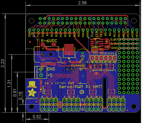

After looking through the datasheets for the RPI and the HAT, we were able to determine a solution. The pin used to control the 5 volt relay is pin 40 or GPIO 21. If we look to the photo to the right, it shows that HEADER pin 25 on CONN 1 is GPIO 21. So we still have connection and access to this pin. What about the 5 VDC that needs to be provided by the raspberry pi? Well this was determined with a meter. We had assumed that the connections for the 5VDC and GND on the HAT was provided by the external power supply for the HAT. We were wrong and this was what we were hoping for. The 5VDC buss that is on the HAT is provided voltage from the RPI, specifically pin 4. If we look at the photo to the top left. We can see that pin 4 is 5VDC.

The photo above shows a cropped fabrication print. What is denoted by the yellow line is the 5VDC. It is shown in this photo that it comes from pin 4 of the RPI. This works how we would like it since we know from testing, that schematic 1, which tried to use the 5VDC from the external PSU from this unit to power the relay. Now that we know that it is possible to use the 5v bus on the HAT, we can continue to use schematic three for a setup.
To confirm that the mask detection camera works for two people, Charlie brought the mask detection camera to Jon for the two of them to be in front of the camera. The team is about 2.5 feet away from the camera. This is the in the event that a parent and a child must be detected at the same time. Charlie also tested the camera with family and was able to scan five people at the same time. More than two people detected will not be required as people in the background may interfere with the results.


Week 18: 9/4 - 9/10
In the eighteenth week:
Jon
We needed to come up with a plan on how to engage and disengage the magnetic lock. The original goal was to use the GPIO's from the Raspberry Pi to do this. This would not work. The following is the problem we came across and how we plan on solving this problem.
What?
The magnetic lock power supply on the control side utilizes 5V to 24V to engage and disengage the the magnetic lock. We had planned on utilizing the GPIO from the Raspberry Pi to control this.
Problem:
However, the GPIO outputs from the Raspberry Pi uses 3.3V which is not enough to control the lock. A minimum of 5VDC is needed.
Possible Solution:
To use the 5VDC from the Raspberry Pi to actuate a 5volt relay and to supply power over the relay to open and close the door. The issue I see here is overloading the 5Volt rail from the Raspberry Pi. So this needed to be tested to see if this was possible. The first test was to see how much current was pulled when using the power supply to supply the 5VDC for the opening of the door. The Raspberry Pi here would supply the 5VDC to energize the relays solenoid and the 3.3VDC from the GPIO would be used as a signal.
The following schematic shows what was the first test.
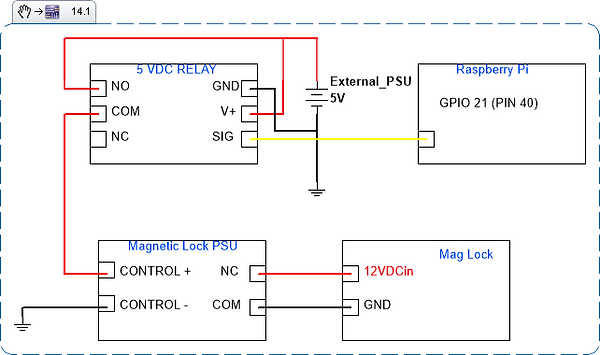
The photo above shows the schematic of the first test done. This shows using the GPIO 21 from the Raspberry Pi to control the signal input for the relay. The 5 volt relay part number JQCF-5VDC-C utilizes a 3.3V input signal to tell the relay to turn on and off. This works since the GPIO on the Raspberry Pi put out a voltage of 3.3V. The 5Volts is going to come from an external power supply. This power supply is for the pan and tilt mechanism but it can be used for testing here. The 5Volts would be connected to the Vin on the Relay and GND to GND. Then, a parallel connection will be made to connect to the normal opened side of the relay and the common side connected to the Control + of the magnetic lock PSU.
While these seemed that it would work, it did not. Using my multimeter, I was getting a reading of -16V across V+ and GND. I made sure my connections were sound and I even disassembled and reassembled the circuit and still garnered the same results. Because of this, this idea was scrapped since I did not want to risk shorting out any of the components.

The schematic above shows the second round of testing. This consisted of utilizing both the 5VDC bus from the Raspberry Pi from pin 2, ground from pin 6, and the 3.3V signal voltage from pin 40(GPIO 21). These connections were made to the 5 volt relay respectively. However, the 5 volts to control the magnetic lock power supply came from the external power supply. This was done so that current measurements can be made. These current measurements were taken when ever the relay would kick on. So from pin 2 a current measurement was taken as well as a current measurement taken from the external power supply to the magnetic lock PSU.

Using my multimeter in series from pin 2 from the Raspberry Pi to the Vin on the relay, a spike current rating of 64.15 mA was seen.

Using the multimeter in series with the external power supply positive voltage output and the normally opened connection on the relay, a current rating of 2.38 mA was seen.

Since this seemed to work with out any errors, a length test shortly took place. Code was written in order for the Raspberry Pi to control the magnetic lock to simulate use of the system over a typical eight hour work day. A base of twelve persons entering per hour was used. This does not include people leaving as that would be in the use of the external exit push button. Twelve persons per hour means the RPI should open the door every five minutes. Charlie and Jon believe that setting the RPI to hold the relay closed for five seconds is enough time to open the door. This took place over a span of over eight hours on 9/9/2022 and the system worked with no issues. Upon inspection everything was as it should be with no damaged components. The following video is of Jon explaining how the circuit is working while set up by following scehmatic 2.
The next experiment is of the following schematic, schematic 3.

The schematic above shows the 5 volts from the RPI bus supplying voltage to both the magnetic lock PSU through the relay and to the relay to provide power to the solenoid. Using a bread board to act as a 5 Volt bus.
This was a concern because using the 5 volts from the RPI means that we were using some of the current that is being provided from the power supply power voltage to the RPI. Since this was the setup that was going to be connected to the RPI that was also controlling the thermal imaging camera, the mask detection camera, and the motor shield. However, the motor shield does have its own power supply to power the servos so this is not a huge concern here.
Once the above circuit was set up, current measurements were made. From Pin 2 from the RPI to the "5 volt buss on the bread board, a current reading of 65.27 mA was observed. This was actually less than what schematic 2 produced which was a total of 66.53 mA. The power supply provides 3.5 Amps of current to the RPI. With the RPI using only 65.27 mA of current or 1.86% of total current, this setup seemed ideal for use.
The above video shows how schematic 3 is setup up and how it works. Just like with schematic 2, this was tested. Using a base of twelve people entering per hour, this system would disengage the lock for five seconds every five minutes. This was done over a span of 8 hours.
This test seemed to had worked with no issues what so ever. In order to garner more results, a modification to the test was made. The code was written so that it can disengage and engage the lock fifteen seconds on and fifteen seconds off. This testing was done consistently over a span of two hours to see if this system could operate under a heavy load.
This worked with no issues.
Charlie
Using the diagram below, Charlie attached the the MLX 90640 IR Thermal Camera to the same Raspberry Pi with the Mask detection camera. Four total wires were used: 3.3V, ground, Serial Data and Serial Clock.


For the software aspect of the camera, the first step was to install matplotlib scipy numpy.

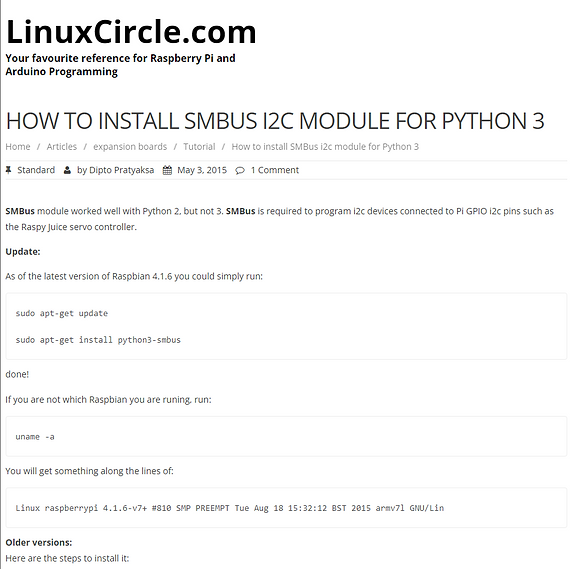
The next step was to install python-smbus. Due to the package being obsolete or missing, an alternative had to be found. Using the following code from LinuxCircle.com, the package was able to be installed.
Step three for the software included installing I2C tools, which was already installed previously.

To ensure that the I2C was enabled, "config" was opened and edited to remove the '#' from the existing code.
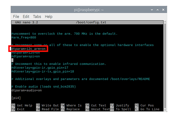
The Raspberry Pi was then rebooted and the IC2 was checked. This was done by entering the following command to check that the number '33' was printed out; this is the I2C address of the MLX 90640.

Two more command lines were entered to install the module to control the Raspberry Pi GPIO channels and the drivers for the MLX90640.


Due to the provided code not working, an alternative source was found on GitHub from the following link:
https://gist.github.com/justinmklam/090d92011c6b7c9510f86b4cb667be92

Once all of the steps were completed, Charlie was able to successfully run the program to detect his heat signature. The problem though is the low fps and resolution that is output from the sensor. Further investigation and tweaking is required to increase both fps and resolution. Charlie's temperature below show a max temperature of 34.7 degrees Celsius.

Week 17: 8/28 - 9/3
In the seventeen week:
Jon
Continued to assemble some of the components.
Above you can see the pimoroni camera with the soldered pins. The photo on the right shows the pins with the 90degree connector attached. This is going to be the orientation that we will connect our wiring so that it stays out of the way of the camera lens it self.
The photo to the left shows the parts used for the pan and tilt system. The photo on the right shows the system in mid build.
Here we can see the pan and tilt assembly built with the exception of the base. The kit was missing some parts. This will be shown in the following photos.
The video above shows how connecting 5VDC to the power supply can also actuate the lock to engage or disengage. This terminals are where the Raspberry Pi will be connected to so that it may engage and disengage the lock. More explanation in the video.
Here this video shows the Raspberry Pi controlling a 5VDC relay. This was to prove that the Raspberry Pi can 'open' and 'close' the door.
Assembly of some of the components also took place. Goal here was to get somethings mounted to the 'wall' of the door mock up. Photo on the left shows the components that are going to be used. The photo on the right shows the receptacle prewired with pigtails so that I may add an external power source from the home.
The enclosure holding the components for the magnetic lock is mounted as well as a double gang steel electrical box. This box is where our 120VAC from the home will come in to power our system. Levels show that everything is level on the structure.


This is the pimoroni camera. With both normal pins and 90degree pins.


To the left is a photo of the base for the pan and tilt. The white mounting brackets seen in the photo are the incorrect ones.
I mounted one of the brackets and cut off the elongated mounting points to see if it would fit and it does not. Further modifying is required. Most likely will have to make out own custom base.


Charlie
Followed a tutorial on an existing mask detection system using the "easy" method. Due to the age of the tutorial, some of the information was outdated. The current version of Tensorflow was not working with Python3. OpenCV had to be reinstalled and updated again because of ModuleNotFoundError "no module name cv2 in python". Q-engineering sight was used to find and install the correct version of tensorflow. Once Tensorflow was installed a third time, the face_mask_detection.py was able to run.

The figure above shows the error "Module, which needed to be corrected in order for the program to run.

The figure above is the code that was used in the terminal to uninstall the current version of Tensorflow that is incompatible with Python3 and reinstall another version.

Once the new installation of Tensorflow was complete, the Face Mask Detector program was able to run successfully. The figure above shows Charlie not wearing a mask, and the display reading "No Face Mask Detected".

Charlie then put on a blue mask, and the camera was able to detect its presence. The display now reads "Face Mask Detected".


To test the accuracy of the Face Mask Detector, Charlie partially moved his mask slightly below his nose (left) and below his nose (right). Based on the two figures above, the camera has the possibility of being fooled by a person who is not wearing a mask properly.

The Face Mask Detector was then tested in lower lighting conditions. Here, Charlie's face is only illuminated by the light emitting from the monitor. The camera is still able to detect his face clearly with no mask.

Again, Charlie's face is only illuminated by the light emitting from the monitor. The camera is still able to detect his face is fully covered by the mask.


To test the accuracy of the Face Mask Detector in lower lighting conditions, Charlie partially moved his mask slightly below his nose (left) and below his nose (right). Based on the two figures above, the camera has the possibility of being fooled by a person who is not wearing a mask properly.
Group
Jon and Charlie got together on 8/30 to work on wiring and setting up the door lock mechanism. This was done on a bench to verify functionality prior to actually fastening anything down on the door mock up.


One of the first things done was weigh the steel plate to the magnetic lock. This plate will eventually be bolted to the door so that the magnetic portion of the locking system may engage this plate. The plate weighs 574 grams (1.26 lbs). This is more than 50% lighter then the previous 3 lbs we had assumed it weighed.


The above photos show the main locking unit of the magnetic lock assembly. This weighed 978 grams or 2.16 lbs. This shall be mounted to the door frame its self. The reason why we wanted to weigh these components, is because we had a concern with having the door mock up being top heaving with added components. After weighing this components, we assess that not major effects shall take place to the frame of the project.

We started to mount the components to enclosure. Here we can see the exit door switch control module screwed down to the plate that then gets screwed into the enclosure.

This photo shows the plate installed inside the enclosure. The 12volt power supply is also screwed to the plate.


The photo to the left shows what the enclosure looks like with the lid closed. The photo shows everything installed inside the enclosure with all wires connected. In this state, the magnetic lock with the exit push button can be tested for functionality.
The above video shows how we got the mag lock to function.
This video shows the idea we came up with for mounting the equipment 'inside' or on the 'interior wall'
Week 16: 8/21 - 8/27 - This marks the beginning of Senior Design
In the sixteen week:
Jon
Jon worked with a really good friend named Dennis, who has worked a good part of his life as a carpenter. Dennis had helped Jon out on making sure the door mock up was where it needed to be. A list of items was made after having the conversation about the door with Professor Notash.
This includes:
-Square up the structure and evening out all gaps
-Stop the door from closing by its self
-Have the structure 90 degrees standing up from the floor so that it is not leaning back anymore.
-Remove the temporary wall and place the permanent wall
With the help of Dennis, the door and the particle board wall was removed. This was needed to be done so that there is no weight on the structure so that we can square up the frame. Something learned here was when building a frame with a door, it is imperative to square the door jam up first. If not, everything down the line will be out of square as well.

This photo is of the upper most corner of the door jam. Using a framing square, it is easily seen how much out of square the door jam was. With the gap in the upper left corner, it was determined that the structure was being pulled to the right.


In order to make the door jam square, diagonal braces were added to the back right side of the structure. This is was placed on the other side of where the wall would be mounted. Once these braces were added, the door jam was squared.

This photo shows the framing square proving that the door jam is now square. As stated earlier this was because of the diagonal braces that were added to the frame. Now that the door jam is square. The rest of the structure can be tackled.

The door was again mounted on the squared door jam. Using a speed square that also counts as a level, it can be seen that the door is not level and does not lean.

The door, when closed, is still not flush. It still closes at an angle which is seen in the photo to the left. This is due to the vertical 2x4 that is seen in the same photo. It needs to be moved over and the right side of the frame needs to be square.

The line marked with sharpie can be seen to the right of the vertical 2x4. That shows where it was. It was moved over 3/8" inch to the left. This was done so that the 'wall' portion of the door mock up can also be square. This was paramount so that the sheet of ply wood used to be a wall can be mounted correctly with no issues on either side. The framing speed square is used to show that the frame is indeed square.

This is how the structure stands now that it is square. It is easily seen that the gap between the door and the center stud is the same from top to bottom. The door does not drag any more when opening and closing. The diaganol braces that go from the side of the frame to the rear were also adjusted so that the structure does not lean back any more. When it was leaning back, the door would close by its self. This would make it difficult to go in and out of in a real work application

A short piece of 2x4 was cut to fit the inside width of the open portion of the structure(where the wall would be). This piece of 2x4 in this application is called a kicker. It is added to not only add rigidity to the frame but to also fix any vertical studs that are not 100% straight. In this case the center rand right outermost stud bowed inwards so a kicker was added to make sure the studs were parallel with one another. A level shown in the picture shows that the kicker is indeed parallel with the ground.

This is just another angle of the kicker now screwed into the horizontal studs.

Lowe's has a table saw big enough to cut ply wood. A measurement was done to the outside of the center and right most stud to the top of the structure. This gave us 80.01cm (31.5") x 207.01(81.5"). Lowe's kindly cut the ply wood to spec. The plywood was then mounted to the structure.Now we have our wall that covers the entirety of its side.


Now that the whole structure is square and the wall is mounted, it was ok to cut the diagonal braces flush with its corresponding stud.
Charlie
Charlie used an STL file for a Raspberry Pi case for the 7" display. This was printed correctly on the first try, and fit snugly on the display. Due to lack of screws, he did not fully put everything together on this day.

The figure below shows the fit of the 3D printed case for the 7 inch display. It sits on top of the casing and the gaps showing are due to the lack of screws to hold it in place.

While waiting for the screws to come in, the following two models were also printed for the 7 inch display.


The Raspberry Pi 4 was able to be screwed on to the display panel.

The display panel came with a ribbon cable as well as four different colored wires. Using a guide from thepihut.com, Charlie put the 7 inch display together using the red, black and ribbon cable. The other two cables were considered obsolete for the design and were not needed. This set up will need to be modified once more to accommodate for the Raspberry Pi hat, which will be used to connect the tilting mechanisms.

The figure below show that outer casing installed to protect the connected components. This includes the Raspberry Pi board, board for the 7 inch display and three cables. For now, the fan will be excluded to fit all the components. This may be needed later on in the future if all the combined processes begin to overheat the Raspberry Pi.

The video below is an initial boot for the 7 inch display. As can be seen from the video, the touch screen display appears to be working well without the other two cables. Some required updates can also be seen in this video.
Using an STL found online, Charlie printed a case for the 3.5 inch display, which is shown below.

Unfortunately, the case was meant to house another type of 3.5 inch display with larger bezels, so the display did not fit correctly.

The display panel was then imported into TinkerCAD where it was modified to fit the smaller bezels of the display that was purchased. The modified model and print are shown below. It was overall successful, though some sanding will be required to improve the look of the front of the panel.


Using TinkerCAD, a custom made enclosure was created for the 'Exit' switch button. This produced better results than the previously printed enclosure for the switch. Another modification may be needed for the screws.


Week 15: 8/14 - 8/20
In the fifteenth week:
Charlie
Charlie used an STL file of an enclosure from Thingiverse that he modified for the purpose of protecting the components of the 'Exit' switch. Modifications that were made were incorrect, so that enclosure, unfortunately, did not fit.

The figure below show that the attempted modification and print were far too small. This was due to the incorrect units that were set in TinkerCAD.

Group
Charlie and Jon got together to finish building the door mock up. When the door was opened, the structure would lean forward, causing the door to drag on the floor. Additional diagonal supports were needed in order for the door to open properly. The supports would hold the vertical frame upward so that it would not lean forward once the door was opened. The wall was also installed. The particle board used was not enough to cover the entire wall. This was due to using left over wood that was available as opposed to adding more purchases to the budget. We are waiting on a confirmation if we need to change the wall out and cover it with a full sheet of plywood.

This is the door somewhat opened and it can be seen that it is touching the floor

Another short piece of 2x4 was added to each side of the structure to help added rigidity to the frame. This did not stop it from leaning forward but it did prevent it from going out of square.

Diagonal supports were added to the newly added 2x4. This helped keep the structure upright when the door was opened. This was done to both sides as seen below.


The photo above shows particle board mounted on the structure to create a wall.
Week 14: 8/7 - 8/13
On the fourteenth week:
Jon
Jon did bench testing and assembly of the Magnetic Lock. This was done to verify that the components do work out of box and to also take current and voltage measurements.
As seen above from the Mag Lock Measurements Vs. Specification table, the actual Power reading from the magnetic lock is almost a third of a watt higher than what was previously calculated as seen in the Proposed Power Budget Table. This may be due to the gauge of wire used from the power supply to the magnetic lock. A test with a larger gauge wire is needed to verify this.
Further testing was done. This was done just like how it was done previously. A wire of about 7.62 meters (25 feet) long was used just for testing. This wire consisted of two 16 AWG conductors and the ends of the wires were soldered. A continuity test was done between both of the leads to the magnetic coil of the magnetic lock.
Another current reading was taking. A reading of 326.6 mA can be seen in the photo above. If using Ohms Law, V = I*R with I = 326.6mA and R = 33ohms, this would give us a voltage of 10.7778. So why the voltage drop? The board that the input voltage connects to has circuitry to prevent the lock from shorting out or burning up.
Overall, the power supply used for the lock will suffice. Next will have to test using the Raspberry Pi to unlock or disengage the steel plate.
Charlie
Encountered issues with booting the Raspberry Pi 4. After some troubleshooting by testing the micro SD card in different computers, he discovered that it was a hardware issue with the micro SD card. After taking a closer look at the chip, he was able to determine that a hairline crack was the cause of the reading error.
Charlie ordered a two pack of micro SD cards to be shipped overnight. Once the cards were received, he reinstalled Raspberry Pi OS on the Raspberry Pi.
By following a tutorial online, Charlie was able to install TensorFlow and OpenCV on the Raspberry Pi.
OpenCV was installed quickly, but TensorFlow required some troubleshooting.
The results here show that OpenCV was successfully installed.
After some research, the problem was solved by downgrading the protobuf package to 3.9.2. The current version was 4.21.5 which was incompatible with Python3.
The results here show that TensorFlow was successfully installed on the Raspberry Pi.
Group
Continued communication and updated each other on their respective progress. Both Raspberry Pis are ready for use and testing.


Started to stage some of the items. A cable with a ground prong is used to power the PSU for the Mag Lock. There is no ground wire for the PSU, so the ground from the cable was attached to the chassis of the PSU.
Output DC Voltage is being measured here with a Fluke 87 multi meter. Here a reading of 12.18Vdc is seen from COM to NC. NC is where the mag lock would be connected.

Input AC Voltage is being measured. Voltage reading of 122.6 Vac is measured from Hot to Neutral(Black wire to White wire)


The magnetic lock was opened and the wire landing can be seen to the right of the unit.
Wire is needed to connect the PSU to the magnetic lock so the ends of the wires were stripped and tinned so that it makes a solid connection with no wire strands poking out.
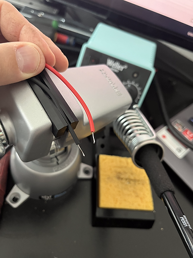
Red and black wires are tinned. The colors were kept so that polarity is not accidentally switched.


The magnetic lock is energized and that is noted with the illuminated red LED magnetic lock.
The Fluke multi meter is set to measure current. DC is measured by placing the meter in series with the circuit that energizes the magnetic lock. A reading of 312 mA is seen. A good pry and tug was done to take the steel plate off the magnetic lock but to no avail. A true test would have to be conducted to make sure that door cannot open.
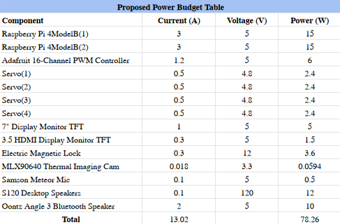
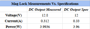


Using a Fluke multi meter to measure the coils resistance,a measurement of 33 ohms can be seen.
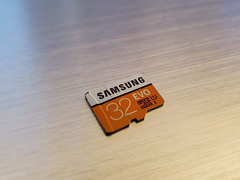

Week 13: 7/31 - 8/6
On the thirteenth week:
Group
Assembled the skeleton structure that consists of the door panel and the frame that will be used as a mock door system for medical facilities. The idea was to follow the 3D rendering of the mock up designed three weeks prior. The hinges of the door were installed on the outside, so that the door swings outwards. This safety issue will be addressed. What is left is to make minor adjustments to make sure the structure is squared up and to start installing the components.
Various tools were used such as
- Saw Horse
- Circular Saw(Skil Saw)
- Jigsaw
- Speed Square
- Tape Measure
- Drill
- Impact Drill


Staging necessary pieces of wood to cut.

First portion of the frame screwed together.
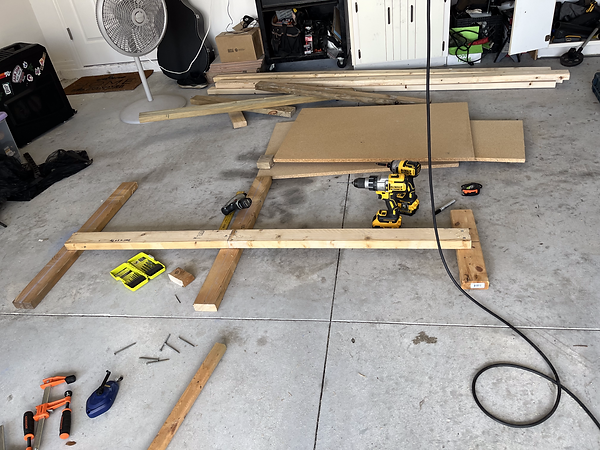
Bottom of frame finished.
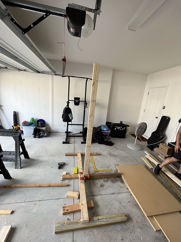
First vertical 2x4 mounted to the base. The farthest right piece of wood for the base was removed and replaced with a longer piece for stability.


Left photo shows us installing the left most vertical 2x4. The right photo shows the speed square being used to make sure the frame is squared up.
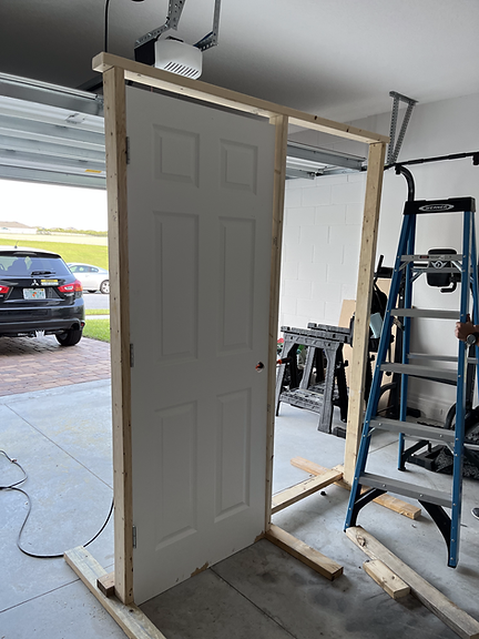

The above two photos show the frame pieced together with the door mounted. What is left is to continue to square up the structure as well as put up the wall. Some components are starting to come in so they will be installed as they come in.
Week 12: 7/24 - 7/30
In the twelfth week:
Jon
Assembled the servo shield and soldered all the joints. Attached it to the Raspberry Pi to check for physical connectivity. Checked all soldered joints with a multimeter to make sure no shorts were accidentally created while soldering.


The above photos show what the servo hat looks like prior to being assembled and soldered.
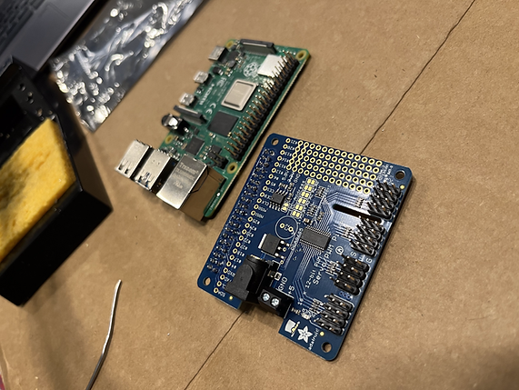
Servo hat assembled and soldered.
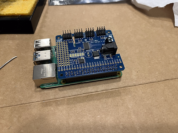
Servo hat assembled and mounted on top of the Raspberry Pi
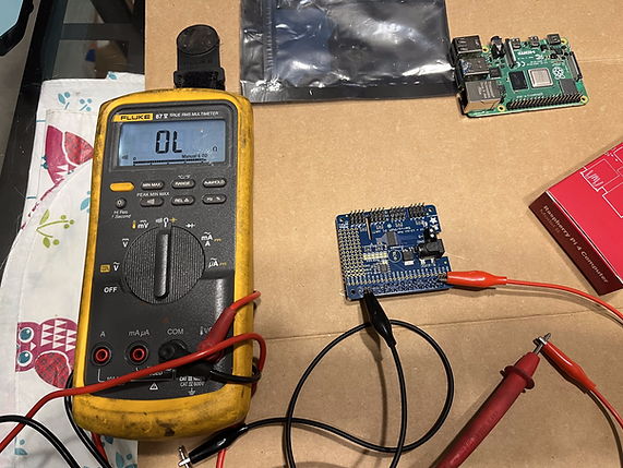
Checking the servo hat with a multimeter for shorts.
Jon continued to work on the website. Jon made edited the Design Engineering Requirements and Design Engineering Specification.
Charlie
Installed the operating system on the Raspberry Pi. Updated the report charts, hyperlinks, table of contents.

Week 11: 7/17 - 7/23
In the eleventh week:
Jon
Ordered and received one of the two Raspberry Pis as well as the servo shield. Continued to order parts for the design phase of the project.
Charlie
Waited for one of the two Raspberry Pis to arrive.

Week 10: 7/10 - 7/16
In the tenth week:
Jon
Made a change of a component of the servo hat needed for the servos. After our Senior Proposal Presentation, one of the panelist had noticed that we had selected a servo hat for Arduino and not for the Raspberry Pi. The Adafruit 16-Channel PWM/Servo HAT & Bonnet for the Raspberry Pi will need to be used in order for the GPIO's on the Raspberry Pi to connect correctly. The following images show the schematic for the HAT for the Arduino and the HAT for the Raspberry Pi. The power supply we have selected for the previously selected HAT will still work for the new HAT. The Servo HAT was ordered as well as both of the Raspberry Pis.

Adafruit schematic for Arduino servo shield

Adafruit schematic for Raspberry Pi servo shield

Input voltage landing site for the Raspberry Pi Servo Hat will work with the power supply selected for use.
A 3D mock up was also created to provide a visual representation on what needs to be built in order to test and implement the H.S.E.S.


Charlie
Modified the numbered weeks for the project timeline as suggested by Professor Notash. He also ordered one of the two Raspberry Pis.
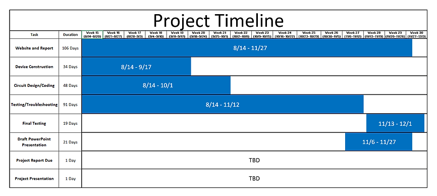
Week 9: 7/3 - 7/9
In the ninth week:
Jon
Redid the block diagram for the H.S.E.S. The changes done to the block diagram include moving the blocks around so that they flow better and are easier to follow. The color of the blocks were also changed.
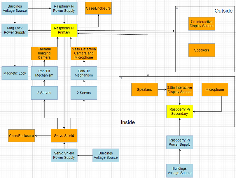
Jon redid the main Flowchart and Block Diagram.
Charlie
Redid the Proposal Timeline and Project Timeline with more accurate dates provided by Professor Notash. He continued working on the report and included descriptions for the block diagrams that Jon redesigned.


Group
Charlie and Jon worked on rewriting and updating the Proposal. The new changes include personal items such as speakers,microphones and the door as well as the lumber needed to build the structure. This structure will be our mock up of a point of entry for a medical facility.

Charlie and Jon presented their Senior Proposal Presentation to Valencia College faculty and the engineering panelist. The feedback received from the panelist is as follows:
Week 8: 6/26 - 7/2
In the eighth week:
Jon
Jon continued to make the changes needed on the website. The Design Engineering Requirements was rewritten to sound concise, clear and straight to the point. The DER needed more specifics for the camera system as well as the COVID-19 questionnaire system. The photo below is the most updated/recent DER.
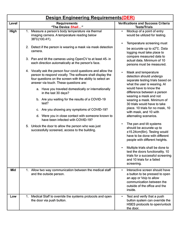
Jon also drilled and assembled Charlie's 3D printed model of the Pan and Tilt system. This was printed to possibly do a proof of concept utilizes this piece of equipment.


Charlie
Week 7: 6/19 - 6/25
In the seventh week:
Jon
Jon celebrated his first Father's Day and then later spent an entire day in the ER to take care of his son.
Jon made more updates to the CAD drawings to reflect the new changes. These changes include removing the vertical structure and replacing it with cameras that pan and tilt. This allows the cameras to move independently and simplifies the goal of having the cameras move and look at an individual. Also, the orientation of the cameras and touch pad were changed. They should be mounted to the opposite side of the door so that when the door is opened, it does not hit anything that is part of the system. The touch screen is setup in a manner where it does not move with the cameras. Jon also modified the HSES Financial Budget.
Charlie
Charlie updated the Proposed timeline and weekly timeline. These were both uploaded to the website. He attempted to 3D print a camera module housing for the purpose of having a tilting mechanism. He then updated the Success Criteria based on the new parts required for the tilting camera system.
Group
As a group, we performed research on how pan and tilt systems work with the Raspberry Pi. We needed to make sure that the Raspberry Pi can control at least four servers, so the Adafruit 16-Channel PWM hat stepper motor controller was added to the project instead of using the A4988 Stepper Motor Driver. The Raspberry Pi does not do PWM well so the use of a external motor controller is needed. We continued to work on adding material to the website as well as working on the Proposal Report.
Week 6: 6/12 - 6/18
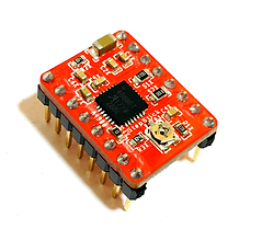

In the sixth week:
Jon
Wrote out the Design Engineering Requirements, Abstract and Description for the HSES. He did research on FLIR and mask detection systems as well as stepper motors and how to control them to obtain a specific degrees. Using a A4988 Stepper Motor Driver and a NEMA17 motor was considered as the driver for the stepper motor. Since the stepper motor would have to rotate a some what heavy load, driver would need to handle enough current to be able to move the weight up and down.
The above photo shows what the A4988 Stepper Motor Driver looks like. This drive could control up to four coils of a motor. It operates at 5V from the controller and has a max output capacity of 35V at 2Amps. The main reason why this was considered is because it can control stepper motors in full, half, quarter, eight, and sixteenth step modes. This is important when considering the accuracy of the height that we needed the cameras to be at. The smaller the step, the more accurate of a movement the stepper motor can make.
This LINK here will show an example of a Raspberry Pi utilizing this driver.
Jon also made updates to the previous CAD drawings which incorporated the camera pan and tilt changes that were later approved by Professor Notash. The new CAD drawings also included more realistic dimensions as well as a door location change as suggested by Professor Notash. Jon also created the Proposal Budget and Proposal Power Budget.
Charlie
Added dimensions to the FADEW diagrams as suggested by Professor Notash and updated the components inside the components box. The FADEW diagrams were again updated to show the new location of the components box. He wrote out the HSES success criteria based on the Estimated Budget Spreadsheet created by Jon. After watching some YouTube tutorials, Charlie was able to create a Gannt Chart of the Proposed Timeline on Excel; this was then uploaded to the website. The website was also updated to replace the FADEW from the homepage with the HSES.
Group
Charlie and Jon looked over the Design Engineering Requirements for both FADEW and HSES to ensure everything from the list provided by Professor Notash was included. They both continued to do research on temperature tracking systems and mask detection systems. Both continued to update each other via texts and phone call on tasks performed and tasks needed to be completed.
Week 5: 6/5 - 6/11

In the fifth week:
Jon
Performed research on LevoUSA, a company that makes wheelchairs that also allow a person to stand. This research was done to find examples of similar project to the Fall Alert Detection Electric Walker (FADEW). He also did research on hub drive and mid drive motors and how they are controlled.
Jon downloaded and experimented with TinkerCAD as a potential software alternative to FreeCAD to create 3D CAD drawings. After receiving feedback from Professor Notash, Jon modified the PDFs with the necessary changes that were wanted. The changes include a two-way communication/interaction between inside personnel and outside individuals (patients, visitors, etc); This would assist the individuals in case of difficulty and all other matters such as postal or other commercial deliveries requiring access and more.
Charlie
Watched tutorial videos on TensorFlow 2.0 and how to use Python to create facial detection systems.
Charlie downloaded and experimented with TinkerCAD as suggested by Jon. He began a rough model of the Fall Alert Detection Electric Walker (FADEW).
Group
Jon and Charlie worked collectively, during a call, to write out a detailed report on the functionality of the Fall Alert Detection Electric Walker. This was a more elaborate document that included the seven aspects that the professor was looking for in each of the ideas.
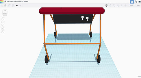
Week 4: 5/29 - 6/4
In the fourth week:
Jon
Updated the Draw.io files to make the suggested changes from Professor Notash. This included formatting the block diagrams and flowcharts to make them more legible. He updated the PowerPoint presentation to include the new block diagrams and flowcharts as well as the rough estimates for the budgets. Jon called the City of Haines City Water Department to set up an appointment with the Chief Operation Lead for Haines City Water. He created a design sketch for the Health Screening System and did research on elevator systems and conveyor systems to see how they could be implemented into the project.
Charlie
Charlie created a design sketch for the Electric Walker idea. He continued watching more tutorials on how to use FreeCAD software in order to be able to create sample designs. He also watched tutorials on how to used dynamic pages on Wix. On the website, he updated the Weekly Minutes with Professor, the Progress Log for weeks one through four, and the Proposed Ideas page. For the Proposed Ideas page, he updated the block diagrams and flowcharts to be larger and more legible, included the group member skills for each idea, updated the budgets for each idea, and included websites for similar systems.
Group
During a call, the group discussed how each project should function and how they should look. This was done to have a better visualization of what each of the group members expected the three ideas to look like. The group later determined what needed to be changed with the group dynamic. This included a discussion on how best to talked the upcoming tasks and deadlines for Tuesday as well as how the group needs to spend more time working collaboratively. Working independently slowed down the process since the group members had to wait for each other's response before moving on with an idea. Working independently also cause some confusion in which resulted in having an Advisor Minutes page and Weekly Minutes with Professor page. As suggested by Professor Notash, the group wrote out a detailed report on the functionality of the Health Screening Entry System that followed the seven requirements to be included in each of the three proposed ideas.
Jon and Charlie did research on mask recognition and on thermal imaging. This includes applicability, brief history, and functionality. The following links are a some of the things viewed.
KINTRONICS Thermal Body Temperature Screen Cameras
https://www.youtube.com/watch?v=EoDFUQsUeN4


The design above shows a drawing of the idea for the Fall Alert Walker. Below the seat of the walker, there is a platform where the battery and Raspberry Pi 4 are placed. The wires coming from the Raspberry Pi 4 are connected to the sensor on the top bar of the walker. This sensor is an accelerometer that will be used to determine if a fall has occurred. The diagram on the right show the general dimensions of a typical walker. This particular model include a basket under the seat. This basket may be modified to house the components.

This is a diagram of the Health Screening Entry System. The system shows the standard dimensions for a door. This front view of the door shows that the device will be installed in both the door and three feet from the door. In the door, there is a deadbolt that is controlled by a motor. This motor is connected via a wire to the components, which contains the Raspberry Pi 4, motor shield and power supply. The ultrasonic sensor will utilize a pulley system with a motor to adjust the height of the device based on the individuals that step on the yellow dot. This yellow dot indicates a three feet distance from the door. Given all the right conditions, the door should unlock and open for the individual that is scanned.
This diagram is the rear side of the door and indicates the cable wires that from from the components box to the motor and deadbolt combination.
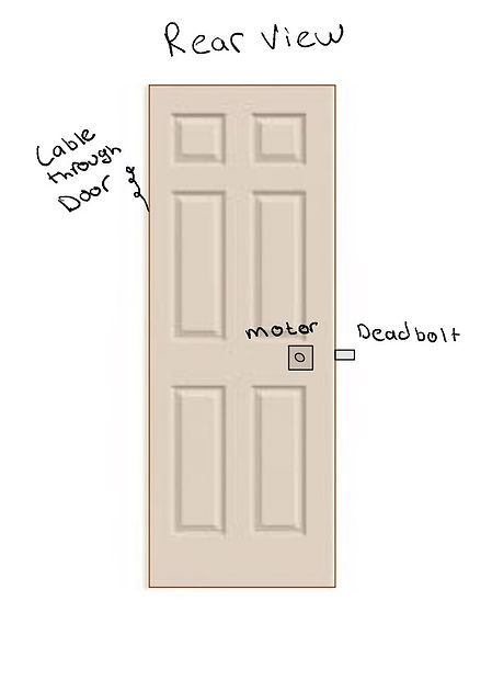
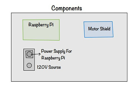
Inside the previously mention component box is a Raspberry Pi 4 Model B along with a Motor Shield and Power Supply. Due to the current needed by the motorized deadbolt, a 120V source will be used.
Week 3: 5/22 - 5/28
In the third week:
Jon
Worked on the PowerPoint presentation for the next meeting. He performed research on battery cells, electric motors, arduino LTE capabilities and walkers. He spent some time learning how to use FreeCAD in an attempt to make a simple model of one of the project ideas. He made block diagrams and flowcharts for the Health Screening Entry System. He edited the current break down of the electric walker idea and elaborated on its tilt/fall capabilities. He created a general budget list for the electric walker. Jon continued editing the website to ensure that it followed the guidelines of the rubric. This included the Time and Effort page and the Advisor Minutes Page.
Charlie
Researched microcontrollers and microprocessors such as the Arduino UNO Wifi Rev2 and the Raspberry Pi 4 Model B. He added some items and created an estimated budget required for the Watercraft idea. He updated the block diagrams for the electric walker and gesture controlled RC car. He organized the website and PowerPoint presentation by continuing to add more information to different pages in the Senior Design Proposal section. Charlie also created a list of items for the group members to take care of to distribute the work load.
Group
During a video call, the group discussed the possible body design of the Watercraft idea. Charlie worked on a rough CAD drawing for the water craft and the both of them performed a rough budget analysis for the idea based on an airboat. The group looked over the materials to be completed by the 4th week. This included website changes, creating drawings for the project ideas and PowerPoint presentation.

This is a simple model of the Watercraft inspired by an airboat design. The small box shown behind the circular disk contains the components needed for the project. This includes the Raspberry Pi 4 as well as the power supply.
Week 2: 5/15 - 5/21
In the second week:
Jon
Organized the files in the shared Google Drive so that they were easy to access. Jon also created the Project Idea page on Wix, which included writing a paragraph description of the ideas as well as their functionalities. Research was done to show similar project ideas that already exist. These can be seen by the hyperlinked texts.
Charlie
Continued to work on the Block Diagrams and Flowcharts and added them to the PowerPoint presentations as was required by Professor Notash. Charlie researched potential items that could be used interchangeably between the project ideas to determine possible sources where they could be purchased and to get a rough estimate of the cost of items.
Group
During a few calls, the group worked together to develop the Block Diagrams and Flowcharts. The group performed research on the types of sensors that may be needed for each project as well as determining if microcontrollers or microprocessors will be used. The research also included an elaboration of the ideas to provide detailed descriptions and functionality of the RC Watercraft.
Week 1: 5/9 - 5/14
In the first week:
Jon
Wrote out detailed descriptions about the proposed project ideas. He also did research on what software to use for block diagrams and flowcharts. He started to develop block diagrams and flow charts for ideas. He did research on how specific aspects of the project should be implemented so that it can properly be added to the block diagrams and flowcharts.
Charlie
Put together the Powerpoint for the first meeting with Professor Notash. He created a Google Account for the group so that sharing documents and any files made would be easier. This same Google Account was used to create a Wix account to start the group website. With Wix, he created a general template for the group to follow. Charlie found a software called Draw.io which he used to create the block diagrams and flowcharts.
Group
Together, Jon and Charlie went over ideas and propositions. In their first meeting with the professor, the group learned about the requirements for the class as well as expectations from the group. After meeting with the professor, the group looked over website layouts created by former and current students and discussed the criteria that must be met for the PowerPoint presentations. This included splitting the work for making the block diagrams and flowcharts. During a call, Charlie and Jon discussed how each of the ideas should be implemented.
Pre-Semester Work
Charlie and Jon met for the first time one week prior to the start of the semester to brainstorm some ideas. Below are some of the initial project ideas.

bottom of page